/MAT/LAW2 (PLAS_JOHNS)
Block Format Keyword This law represents an isotropic elasto-plastic material using the Johnson-Cook material model.
This model expresses material stress as a function of strain, strain rate and temperature. A built-in failure criterion based on the maximum plastic strain is available.
Format
| (1) | (2) | (3) | (4) | (5) | (6) | (7) | (8) | (9) | (10) |
|---|---|---|---|---|---|---|---|---|---|
| /MAT/LAW2/mat_ID/unit_ID or /MAT/PLAS_JOHNS/mat_ID/unit_ID | |||||||||
| mat_title | |||||||||
| E | Iflag | ||||||||
| (1) | (2) | (3) | (4) | (5) | (6) | (7) | (8) | (9) | (10) |
|---|---|---|---|---|---|---|---|---|---|
| a | b | n | |||||||
| (1) | (2) | (3) | (4) | (5) | (6) | (7) | (8) | (9) | (10) |
|---|---|---|---|---|---|---|---|---|---|
| UTS | |||||||||
| (1) | (2) | (3) | (4) | (5) | (6) | (7) | (8) | (9) | (10) |
|---|---|---|---|---|---|---|---|---|---|
| c | ICC | Fsmooth | Fcut | Chard | |||||
| m | Tmelt | Tr | |||||||
Definitions
| Field | Contents | SI Unit Example |
|---|---|---|
| mat_ID | Material identifier (Integer, maximum 10 digits) |
|
| unit_ID | Unit Identifier (Integer, maximum 10 digits) |
|
| mat_title | Material title (Character, maximum 100 characters) |
|
| Initial density. (Real) |
||
| E | Young's modulus. (Real) |
|
| Poisson's ratio. (Real) |
||
| Iflag | Input type flag. 3
(Integer) |
|
| a | Yield stress. 2 (Real) |
|
| b | Plastic hardening parameter b. (Real) |
|
| n | Plastic hardening exponent n. 6
Default = 1.0 (Real) |
|
| Failure plastic strain. Default = 1030 (Real) |
||
| Maximum stress. Default = 1030 (Real) |
||
| Yield stress. (Real) |
||
| UTS | Ultimate tensile stress (engineering
stress). Input
. (Real) |
|
| Engineering strain at
UTS. Default = 1.0 (Real) |
||
| c | Strain rate coefficient
.
Default = 0.00 (Real) |
|
| Reference strain rate. If , no strain rate effect. (Real) |
||
| ICC | Strain rate computation flag. 9
(Integer) |
|
| Fsmooth | Strain rate smoothing flag.
(Integer) |
|
| Fcut | Cutoff frequency for strain rate smoothing. Only available for shell and solid
elements, Appendix: Filtering. Default = 1030 (Real) |
|
| Chard | Hardening coefficient (unloading).
(Real) |
|
| m | Temperature exponent. 13 Default = 1.00 (Real) |
|
| Tmelt | Melting temperature.
Default = 1030 (Real) |
|
| Specific heat per unit volume. 11 (Real) |
||
| Tr | Reference temperature. 11 Default = 298 K (Real) |
Example (Classic Parameter Input)
#RADIOSS STARTER
#---1----|----2----|----3----|----4----|----5----|----6----|----7----|----8----|----9----|---10----|
/UNIT/1
unit for mat
                  Mg                  mm                   s
#---1----|----2----|----3----|----4----|----5----|----6----|----7----|----8----|----9----|---10----|
#-  2. MATERIALS:
#---1----|----2----|----3----|----4----|----5----|----6----|----7----|----8----|----9----|---10----|
/MAT/PLAS_JOHNS/1/1
Steel
#              RHO_I
              7.8E-9
#                  E                  Nu     Iflag
              210000                  .3         0
#                  a                   b                   n             EPS_max            SIG_max0
                 270               450.0                 0.6                   0                   0
#                  c           EPS_DOT_0       ICC   Fsmooth               F_cut               Chard
                   0                   0         0         0                   0                   0
#                  m              T_melt              rhoC_p                 T_r
                   0                   0                   0                   0
#---1----|----2----|----3----|----4----|----5----|----6----|----7----|----8----|----9----|---10----|
#ENDDATA
/END
#---1----|----2----|----3----|----4----|----5----|----6----|----7----|----8----|----9----|---10----|
Example (Simplified Input - Experimental Data)
#RADIOSS STARTER
#---1----|----2----|----3----|----4----|----5----|----6----|----7----|----8----|----9----|---10----|
/UNIT/1
unit for mat
                  Mg                  mm                   s
#---1----|----2----|----3----|----4----|----5----|----6----|----7----|----8----|----9----|---10----|
#-  2. MATERIALS:
#---1----|----2----|----3----|----4----|----5----|----6----|----7----|----8----|----9----|---10----|
/MAT/PLAS_JOHNS/1/1
Steel (use ultimate tensile stress(UTS) and engineering strain )
#              RHO_I
              7.8E-9
#                  E                  Nu     Iflag
              210000                  .3         1
#              SIG_y                 UTS             EPS_UTS             EPS_max            SIG_max0
                 270               362.8              0.2885                   0                   0
#                  c           EPS_DOT_0       ICC   Fsmooth               F_cut               Chard
                   0                   0         0         0                   0                   0
#                  m              T_melt              rhoC_p                 T_r
                   0                   0                   0                   0
#---1----|----2----|----3----|----4----|----5----|----6----|----7----|----8----|----9----|---10----|
#ENDDATA
/END
#---1----|----2----|----3----|----4----|----5----|----6----|----7----|----8----|----9----|---10----|
Comments
- This is an elasto-plastic material model that includes strain rate and temperature effects with true stress and strain output.
- In this model the material behaves as a
linear-elastic material when the equivalent stress is lower than the plastic yield stress.
For higher stress values, the material behavior is plastic, and the true stress is
calculated as:
(1) Where,(2) Where,- Plastic strain
- Strain rate
- Temperature
- Tr
- Ambient temperature
- Tmelt
- Melting temperature
- If Iflag=0, the Johnson-Cook equation parameters a, b, and n values are entered.
If Iflag=1, experimental engineering stress and stain data can be entered for , UTS and and the parameters a, b and n are calculated and printed in the Starter output file. If the a, b and n parameters cannot be automatically fit, then a Starter warning message will contain important information about changes to the material input.
- The plastic yield stress should always be greater than zero. To model pure elastic behavior, the plastic yield stress will be set to 1030.
- When
reaches the value of
in one integration point, then based on the element type:
- Shell elements: The corresponding shell element is deleted.
- Solid elements: The deviatoric stress of the corresponding integral point is permanently set to 0; however, the solid element is not deleted.
- The plastic hardening exponent, n must be less than or equal to 1.
- The strain rate has no effect on truss elements.
- To eliminate the effect of the strain rate, you can either set the value of c equal to 0 or the reference strain rate ( ) can be set equal to 1030. There is no effect of strain rate when is less than .
- The ICC flag defines the effect of strain
rate on the maximum material stress
. Figure 1 shows the value of for
the corresponding ICC flag.
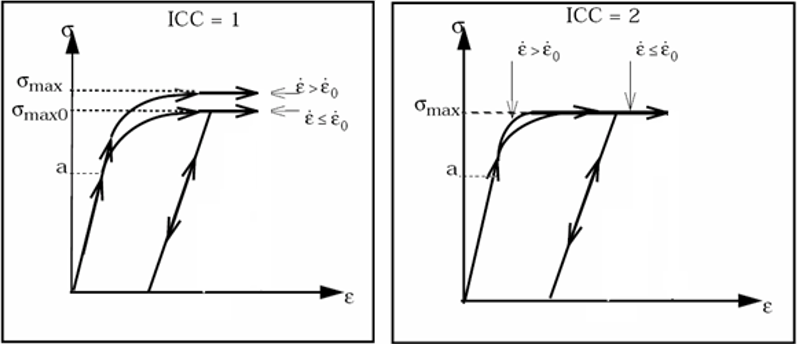 Figure 1.
 - There is no effect of temperature on trusses and beams.
- The temperature is constant ( ), if .
- Adiabatic conditions are assumed for
thermal simulations with initial temperature equal to reference temperature (Tr) and:
(3) Where, Eint is the internal deformation energy.
- The strain rate coefficient, c and reference strain rate must be defined to include thermal effects.
- When /HEAT/MAT (with Iform=1) references this material model, the values of Tr and defined in this card will be overwritten by the corresponding and defined in /HEAT/MAT.
- When the temperature is not initialized using /HEAT/MAT or /INITEMP, the reference temperature (Tr) is also the initial temperature.
- The hardening coefficient is used to describe the hardening model (during unloading). The values of the hardening coefficient should be between 0 and 1.