RD-E: 5300 Thermal Analysis

A heat source moved on one plate. Heat exchanged between a heatsource and a plate through contact, also between a plate and theatmosphere (water) through convective flux.
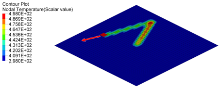
Thermal analysis, like heat exchange (between two contact surfaces, between heat object and surrounding atmosphere though convection or radiation, inside the object through conduction), deformation is due to thermal expansion or heat generated, due to friction can be simulated in Radioss. In this example heat exchange is discussed between a moving heat source and one plate, due to contact and also between plate and atmosphere (water) through convective flux.
ex_53_thermal Figure 1.

Options and Keywords Used

Input Files

The input files used in this example include:
Heat exchange
<install_directory>/hwsolvers/demos/radioss/example/53_thermal_analysis/Heat_exchange/*

Model Description

A heat source with a constant temperature of 800K is moved under imposed displacement on one plate with an initial temperature of 298K. The dimension of the heat source is 5mm x 5mm and the plate is 100mm x 100mm.

ex_53_heat_source
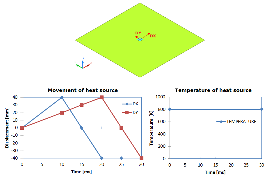
Figure 2. Problem Description

Units: mm, ms, g, N, and MPa

/MAT/LAW2 and /HEAT/MAT are used to describe the aluminum heat source and plate, with the following characteristics:
Material Properties
Initial density
2.8 x 10⁻³ [ g mm 3 ]
Young's modulus
70000 [ MPa ] MathType@MTEF@5@5@+= feaagKart1ev2aqatCvAUfeBSjuyZL2yd9gzLbvyNv2CaerbuLwBLn hiov2DGi1BTfMBaeXatLxBI9gBaerbd9wDYLwzYbItLDharqqtubsr 4rNCHbGeaGqiVu0Je9sqqrpepC0xbbL8F4rqGqFfpeea0xe9vq=Jb9 vqpeea0xd9q8qiYRWxGi6xij=hbba9q8aq0=yq=He9q8qiLsFr0=vr 0=vr0db8meaabaqaciGacaGaaeqabaWaaeaaeaaakeaadaWadaqaai Gac2eacaGGqbGaaiyyaaGaay5waiaaw2faaaaa@3BE6@
Poisson ratio
0.33
Yield stress
206 [ MPa ] MathType@MTEF@5@5@+= feaagKart1ev2aqatCvAUfeBSjuyZL2yd9gzLbvyNv2CaerbuLwBLn hiov2DGi1BTfMBaeXatLxBI9gBaerbd9wDYLwzYbItLDharqqtubsr 4rNCHbGeaGqiVu0Je9sqqrpepC0xbbL8F4rqGqFfpeea0xe9vq=Jb9 vqpeea0xd9q8qiYRWxGi6xij=hbba9q8aq0=yq=He9q8qiLsFr0=vr 0=vr0db8meaabaqaciGacaGaaeqabaWaaeaaeaaakeaadaWadaqaai Gac2eacaGGqbGaaiyyaaGaay5waiaaw2faaaaa@3BE6@
Hardening parameter
450 [ MPa ] MathType@MTEF@5@5@+= feaagKart1ev2aqatCvAUfeBSjuyZL2yd9gzLbvyNv2CaerbuLwBLn hiov2DGi1BTfMBaeXatLxBI9gBaerbd9wDYLwzYbItLDharqqtubsr 4rNCHbGeaGqiVu0Je9sqqrpepC0xbbL8F4rqGqFfpeea0xe9vq=Jb9 vqpeea0xd9q8qiYRWxGi6xij=hbba9q8aq0=yq=He9q8qiLsFr0=vr 0=vr0db8meaabaqaciGacaGaaeqabaWaaeaaeaaakeaadaWadaqaai Gac2eacaGGqbGaaiyyaaGaay5waiaaw2faaaaa@3BE6@
Hardening exponent
0.5
Room temperature
298 [ K ]
Specific heat ρ C p
2.51embim51
Initial temperature for heat source
800 [K] and for plate: 398 [K]
Thermal conductivity coefficient AS
0.23 embim52

Model Method

/HEAT/MAT is an additional material law card used to describe the material thermal character. So the material ID in the material law in /MAT and in /HEAT/MAT must be the same. The thermal parameter defined in /HEAT/MAT will recover the same parameters which are defined in the material law.

Heat capacity provides heat and mass the ability to change the temperature. In engineering and science, it is recommended to use specific heat capacity, which is heat capacity divided by mass, [ J kgK ] MathType@MTEF@5@5@+= feaagKart1ev2aaatCvAUfeBSjuyZL2yd9gzLbvyNv2CaerbuLwBLn hiov2DGi1BTfMBaeXatLxBI9gBaerbd9wDYLwzYbItLDharqqtubsr 4rNCHbGeaGqiVu0Je9sqqrpepC0xbbL8F4rqqrFfpeea0xe9Lq=Jc9 vqaqpepm0xbba9pwe9Q8fs0=yqaqpepae9pg0FirpepeKkFr0xfr=x fr=xb9adbaqaaeaaciGaaiaabeqaamaabaabaaGcbaWaamWaaeaada WcaaqaaiaabQeaaeaacaqGRbGaae4zaiabgwSixlaabUeaaaaacaGL BbGaayzxaaaaaa@3DB3@ in SI unit. Heat capacity is C p = 897 [ J kg K ] = 897 [ N mm g K ] for aluminum. Refer to Material Constants in the Theory Manual Appendices for more information on heat capacity of ordinary material.

For the thermal conductivity coefficient AS, 0.23 [ N mm ms mm K ] . Thermal conductivity k = 230 [ W m K ] = 0.23 [ N mm ms mm K ] for aluminum, and constant thermal conductivity. Set B S = 0 MathType@MTEF@5@5@+= feaagKart1ev2aaatCvAUfeBSjuyZL2yd9gzLbvyNv2CaerbwvMCKf MBHbqefqvATv2CG4uz3bIuV1wyUbqedmvETj2BSbqefm0B1jxALjhi ov2DaebbnrfifHhDYfgasaacH8srps0lbbf9q8WrFfeuY=Hhbbf9v8 qqaqFr0xc9pk0xbba9q8WqFfea0=yr0RYxir=Jbba9q8aq0=yq=He9 q8qqQ8frFve9Fve9Ff0dmeaacaGacmGadaWaaiqacaabaiaafaaake aacaWGcbGaam4uaiabg2da9iaaicdaaaa@3C36@ . Since thermal conductivity k = A S + B S T MathType@MTEF@5@5@+= feaagKart1ev2aaatCvAUfeBSjuyZL2yd9gzLbvyNv2CaerbwvMCKf MBHbqefqvATv2CG4uz3bIuV1wyUbqedmvETj2BSbqefm0B1jxALjhi ov2DaebbnrfifHhDYfgasaacH8srps0lbbf9q8WrFfeuY=Hhbbf9v8 qqaqFr0xc9pk0xbba9q8WqFfea0=yr0RYxir=Jbba9q8aq0=yq=He9 q8qqQ8frFve9Fve9Ff0dmeaacaGacmGadaWaaiqacaabaiaafaaake aacaWGRbGaeyypa0JaamyqaiaadofacqGHRaWkcaWGcbGaam4uaiab gEHiQiaadsfaaaa@40B4@ , then k = A S MathType@MTEF@5@5@+= feaagKart1ev2aaatCvAUfeBSjuyZL2yd9gzLbvyNv2CaerbwvMCKf MBHbqefqvATv2CG4uz3bIuV1wyUbqedmvETj2BSbqefm0B1jxALjhi ov2DaebbnrfifHhDYfgasaacH8srps0lbbf9q8WrFfeuY=Hhbbf9v8 qqaqFr0xc9pk0xbba9q8WqFfea0=yr0RYxir=Jbba9q8aq0=yq=He9 q8qqQ8frFve9Fve9Ff0dmeaacaGacmGadaWaaiqacaabaiaafaaake aacaWGRbGaeyypa0Jaamyqaiaadofaaaa@3C6B@ , in this case.

With /IMPTEMP, imposed temperature will be set on a group of nodes. The source constant temperature is defined for heat source.

ex_53_imposed_temp
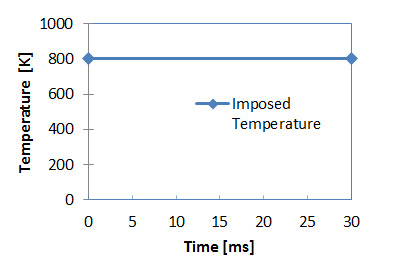
Figure 3. Imposed Temperature for Heat Source
Use /CONVEC to describe the heat exchange between a structural component and its surrounding atmosphere (infinite room).
(1) (2) (3) (4) (5) (6) (7) (8) (9) (10)
/CONVEC/convec_ID/unit_ID
convec_flux_title
surf_IDT fct_IDT sens_ID              
Ascalex Fscaley Tstart Tstop H
The surrounding atmosphere is water with a constant temperature of 298K, which is described in function, fct_IDT (Figure 4).

ex_53_water_temp
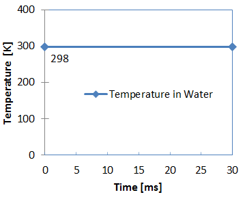
Figure 4. Water Temperature

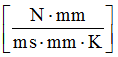
Where, H is the heat transfer coefficient between structural component and its surrounding infinite room with unit [ J s m 2 K ] . In general, the convective heat transfer coefficient for water (free convection) is about 20 - 100 [ J s m 2 K ] and water (forced convection) is about 50 - 10000 [ J s m 2 K ] . Forced convection in water is H = 500 [ J s m 2 K ] = 5 e 4 [ N mm s mm 2 K ] .

In /INTER/TYPE7, heat exchange between the heat source and plate during the contact, is defined Kthe=1 to activated heat transfer between main and secondary.

If Ithe = 1
(1) (2) (3) (4) (5) (6) (7) (8) (9) (10)
Kthe fct_IDK   Tint Ithe_form AscaleK  
Frad Drad Fheats Fheatm    

Ithe_form set to 1 for heat exchange between all pieces in contact.

There are two ways to define heat exchange between contact parts.
  1. Define constant heat exchange coefficient using Kthe ( [ W m 2 K ] in SI unit). In this case, fct_IDK = 0.
  2. If fct_IDK 0, the heat exchange coefficient is the function of contact pressure using this curve and Kthe is the scale factor.
(1) K = K t h e f c t _ I D K ( A s c a l e K , P )
Interfacial heat transfer coefficient, K described conductive heat flux through a unit area of a plate with particular thickness. The range of this heat transfer coefficient can be very large, which will affect the accuracy of simulation. To get a more accurate result, experimental test are required.(2) K t h e = 15000 [ W m 2 K ] = 0.0.15 [ N mm ms mm 2 K ]

Set Fheats and Fheatm to 0, to not consider heat friction.

Results

Figure 5 shows nodal temperature at time 10[ms], 20[ms] and 30[ms]. Part of heat transferred to plate through contact. Therefore, the temperature under the trace increased. The temperature on the plate decreased during the time, due to the convection with water.

ex_53_nodal_temp
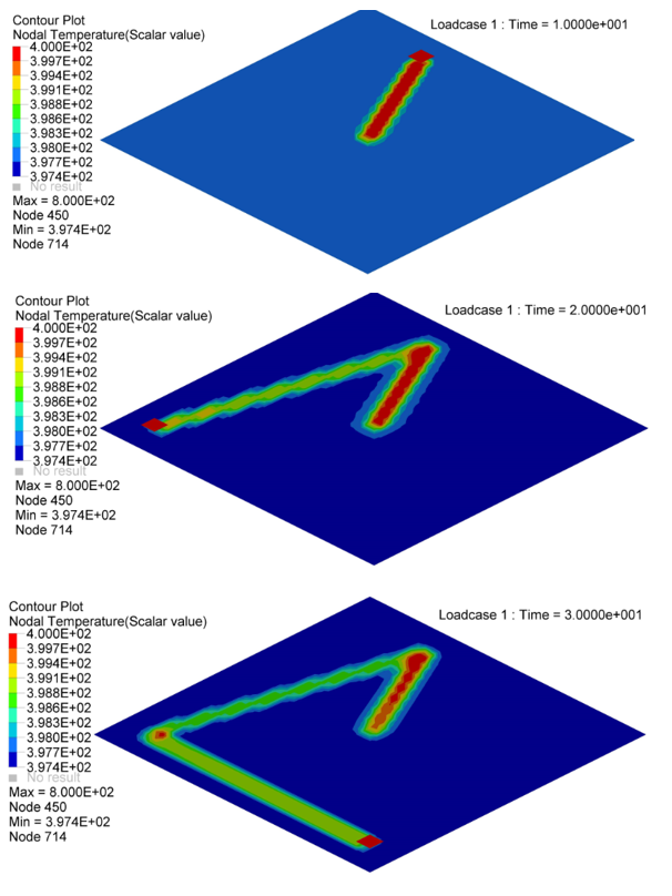
Figure 5. Nodal Temperature in Plate at time=10[ms], 20[ms] and 30[ms]
The nodal temperature on Nodal N641, N1034, N958 and N1708 are illustrated in Figure 6.
  1. Nodal N641 is not under trace. The temperature changed, only due to convection with water.
  2. Nodal N1034, N958 and N1708 are under trace. At first the temperature decreased before the heat source began, due to convection with water, and then increased, due to the heat exchange from the heat source through contact. Once the heat source is removed, the temperature decreased again, due to the heat conduction inside the material and convection with water. So the slope of the temperature decrease is much larger than N641 (only convection).

    ex_53_nodal_temp2
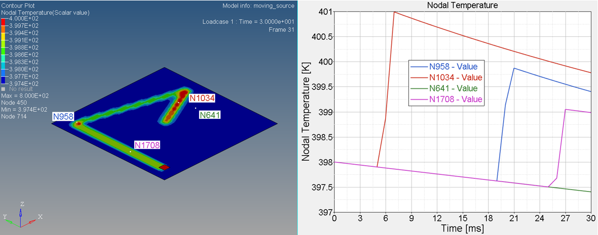
    Figure 6. Temperature on Nodal N641, N1034, N958 and N1708