RD-E: 2300 Brake

A frictional mechanism is studied, which consists of a brake system, defined by a disc pinched between two pads.

The main aspects of the model are the initial rotary motion of the disc and the contact between the disc and the pads with friction and heat transfer. A comparison of the simulation results and an analytical solution is provided in this example.

ex_23_brake
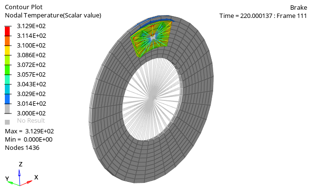
Figure 1. Temperature contour of the brake with friction

Options and Keywords Used

  • /BRICK elements
  • /MAT/LAW2 (PLAS_JOHNS) (Isotropic elasto-plastic material using the Johnson-Cook material model)
  • /INTER/TYPE19 (Multi-usage impact interface; consideration of heat transfer and heat friction is possible)
  • /HEAT/MAT (Describes thermal parameters for thermal analysis)
  • /PROP/TYPE14 (SOLID) (Defines the general solid property set)
  • /BCS (Boundary condition)
  • /INIVEL/AXIS (Initialize both translational and rotational velocities on a group of nodes in a given coordinate system)
  • /CLOAD (Defines a concentrated force or moment applied to each node of a prescribed nodal group)

Input Files

The input files used in this example include:

<install_directory>/hwsolvers/demos/radioss/example/23_Brake/

Model Description

The objective of this example is to demonstrate the simulation of a friction mechanism using Altair Radioss.

Units: kg, mm, ms, GPa

The brake system consists of a disc with a radius of 100 mm, a width of 50 mm, a thickness of 5 mm, and mass = 0.914 kg clamped between two brake pads which are 5 mm thick and weigh 0.06 kg each. The parts are modeled using brick elements using the HEPH (Isolid=24) element formulation.

The disc has an initial rotational velocity of ω 0 = 0.5236   rad ms MathType@MTEF@5@5@+= feaagKart1ev2aqatCvAUfeBSjuyZL2yd9gzLbvyNv2CaerbuLwBLn hiov2DGi1BTfMBaeXatLxBI9gBaerbd9wDYLwzYbItLDharqqtubsr 4rNCHbGeaGqiVu0Je9sqqrpepC0xbbL8F4rqqrFfpeea0xe9Lq=Jc9 vqaqpepm0xbba9pwe9Q8fs0=yqaqpepae9pg0FirpepeKkFr0xfr=x fr=xb9adbaqaaeGaciGaaiaabeqaamaabaabaaGcbaGaeqyYdC3aaS baaSqaaiaaicdaaeqaaOGaeyypa0JaaGimaiaac6cacaaI1aGaaGOm aiaaiodacaaI2aGaaeiiamaalaaabaGaaeOCaiaabggacaqGKbaaba GaaeyBaiaabohaaaaaaa@4377@ . The initial rotational velocity is defined using the /INIVEL/AXIS keyword. This results in an inertia of 5712.5 kg/mm2. A rigid body is created within the inner diameter of the disc. The main node of this rigid body is the center of the rotation and is constrained in all DOFs, except rotation around Y-axis.

A rigid body is created on the outside face of each brake pad. To simulate braking, a concentrated force of 0.3 kN is applied to the main node of each rigid body attached to the two pads. The pads then contact each side of the disc.

The contact between the disc and pad is modeled using a surface to surface contact /INTER/TYPE19 with the heat contact flag activated which allows the heat generated by friction to be turned into energy. A Coulomb friction coefficient of 0.3 is defined in the contact interface.

fig_23-1
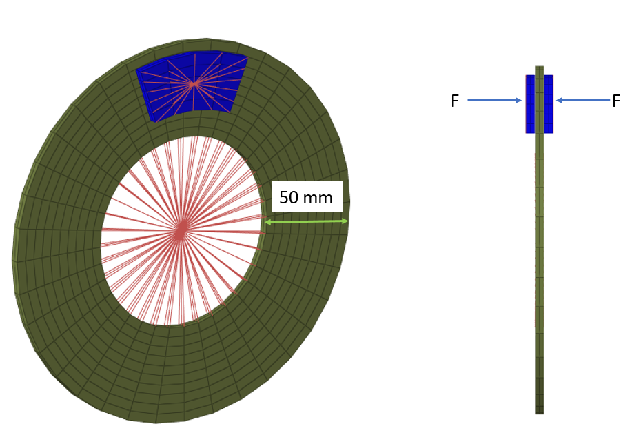
Figure 2. Brake Model

The material model used for the disc and pad is an isotropic elasto-plastic law (/MAT/LAW2) using the Johnson-Cook plasticity model. To model heat transfer between the disc and pad, thermal parameters for the material must be defined in /HEAT/MAT and use the same mat_ID as the /MAT/LAW2 material. When /HEAT/MAT is used with a material, the parameters entered in /HEAT/MAT are used, instead of the thermal parameters in /MAT/LAW2.

The disc is modeled using typical steel material properties with the following thermal parameters:
Material Properties
Initial temperature
300 [ K ]
Specific Heat per unit volume ( ρ C p )
0.00244 [ J m m 3 K ] MathType@MTEF@5@5@+= feaagKart1ev2aaatCvAUfeBSjuyZL2yd9gzLbvyNv2CaerbuLwBLn hiov2DGi1BTfMBaeXatLxBI9gBaerbd9wDYLwzYbItLDharqqtubsr 4rNCHbGeaGqiVu0Je9sqqrpepC0xbbL8F4rqqrFfpeea0xe9Lq=Jc9 vqaqpepm0xbba9pwe9Q8fs0=yqaqpepae9pg0FirpepeKkFr0xfr=x fr=xb9adbaqaaeaaciGaaiaabeqaamaabaabaaGcbaWaamWaaeaada WcaaqaaiaadQeaaeaacaWGTbGaamyBamaaCaaaleqabaGaaG4maaaa kiaadUeaaaaacaGLBbGaayzxaaaaaa@3C6D@
Thermal conductivity coefficient A for solid phase
0.02 [ k W m m K ] MathType@MTEF@5@5@+= feaagKart1ev2aaatCvAUfeBSjuyZL2yd9gzLbvyNv2CaerbuLwBLn hiov2DGi1BTfMBaeXatLxBI9gBaerbd9wDYLwzYbItLDharqqtubsr 4rNCHbGeaGqiVu0Je9sqqrpepC0xbbL8F4rqqrFfpeea0xe9Lq=Jc9 vqaqpepm0xbba9pwe9Q8fs0=yqaqpepae9pg0FirpepeKkFr0xfr=x fr=xb9adbaqaaeaaciGaaiaabeqaamaabaabaaGcbaWaamWaaeaada WcaaqaaiaadUgacaWGxbaabaGaamyBaiaad2gacqGHflY1caWGlbaa aaGaay5waiaaw2faaaaa@3EC0@
Lagrangian heat transfer formulation
Iform=1
Temperature of melting point
2000 [ K ]
The pad material and thermal properties are:
Material Properties
Initial density
7.3 e-06 [ k g m m 3 ] MathType@MTEF@5@5@+= feaagKart1ev2aqatCvAUfeBSjuyZL2yd9gzLbvyNv2CaerbuLwBLn hiov2DGi1BTfMBaeXatLxBI9gBaerbd9wDYLwzYbItLDharqqtubsr 4rNCHbGeaGqiVu0Je9sqqrpepC0xbbL8F4rqqrFfpeea0xe9Lq=Jc9 vqaqpepm0xbbG8FasPYRqj0=yi0dXdbba9pGe9xq=JbbG8A8frFve9 Fve9Ff0dmeaabaqaciGacaGaaeqabaWaaeaaeaaakeaadaWadaqaam aalaaabaGaai4AaiaacEgaaeaacaGGTbGaaiyBamaaCaaaleqabaGa ai4maaaaaaaakiaawUfacaGLDbaaaaa@3D0B@
Young's modulus
160 [ G P a ] MathType@MTEF@5@5@+= feaagKart1ev2aaatCvAUfeBSjuyZL2yd9gzLbvyNv2CaerbuLwBLn hiov2DGi1BTfMBaeXatLxBI9gBaerbd9wDYLwzYbItLDharqqtubsr 4rNCHbGeaGqiVu0Je9sqqrpepC0xbbL8F4rqqrFfpeea0xe9Lq=Jc9 vqaqpepm0xbba9pwe9Q8fs0=yqaqpepae9pg0FirpepeKkFr0xfr=x fr=xb9adbaqaaeaaciGaaiaabeqaamaabaabaaGcbaWaamWaaeaaca WGhbGaaiiuaiaacggaaiaawUfacaGLDbaaaaa@3A6B@
Poisson ratio
0.3
Initial temperature
300 [ K ]
Specific Heat per unit volume ( ρ C p )
0.004 [ J m m 3 K ] MathType@MTEF@5@5@+= feaagKart1ev2aaatCvAUfeBSjuyZL2yd9gzLbvyNv2CaerbuLwBLn hiov2DGi1BTfMBaeXatLxBI9gBaerbd9wDYLwzYbItLDharqqtubsr 4rNCHbGeaGqiVu0Je9sqqrpepC0xbbL8F4rqqrFfpeea0xe9Lq=Jc9 vqaqpepm0xbba9pwe9Q8fs0=yqaqpepae9pg0FirpepeKkFr0xfr=x fr=xb9adbaqaaeaaciGaaiaabeqaamaabaabaaGcbaWaamWaaeaada WcaaqaaiaadQeaaeaacaWGTbGaamyBamaaCaaaleqabaGaaG4maaaa kiaadUeaaaaacaGLBbGaayzxaaaaaa@3C6D@
Thermal conductivity coefficient A for solid phase
0.02 [ k W m m K ] MathType@MTEF@5@5@+= feaagKart1ev2aaatCvAUfeBSjuyZL2yd9gzLbvyNv2CaerbuLwBLn hiov2DGi1BTfMBaeXatLxBI9gBaerbd9wDYLwzYbItLDharqqtubsr 4rNCHbGeaGqiVu0Je9sqqrpepC0xbbL8F4rqqrFfpeea0xe9Lq=Jc9 vqaqpepm0xbba9pwe9Q8fs0=yqaqpepae9pg0FirpepeKkFr0xfr=x fr=xb9adbaqaaeaaciGaaiaabeqaamaabaabaaGcbaWaamWaaeaada WcaaqaaiaadUgacaWGxbaabaGaamyBaiaad2gacqGHflY1caWGlbaa aaGaay5waiaaw2faaaaa@3EC0@
Lagrangian heat transfer formulation
Iform=1
Temperature of melting point
2000 [ K ]

Results

The time to stop the disc can be calculated using the following formulas and model inputs.

The total normal contact force between the pads and the disc is FN = 0.6 kN and Coulomb friction coefficient= 0.3.

The tangential friction force on the surface of the disc is calculated as FT = 0.3 x FN = 0.18 kN. The orthogonal project from the disc’s center axis to the force application point is r = 77.528 mm. This results in a torque around the axis of the disc of,

T = r x FT = 13.95504 kN*mm

From this, an angular deceleration is calculated as:(1) α= T I =0.0024429  rad ms 2 MathType@MTEF@5@5@+= feaagKart1ev2aaatCvAUfeBSjuyZL2yd9gzLbvyNv2CaerbuLwBLn hiov2DGi1BTfMBaeXatLxBI9gBaerbd9wDYLwzYbItLDharqqtubsr 4rNCHbGeaGqiVu0Je9sqqrpepC0xbbL8F4rqqrFfpeea0xe9Lq=Jc9 vqaqpepm0xbba9pwe9Q8fs0=yqaqpepae9pg0FirpepeKkFr0xfr=x fr=xb9adbaqaaeGaciGaaiaabeqaamaabaabaaGcbaGaeqySdeMaey ypa0ZaaSaaaeaacaWGubaabaGaamysaaaacqGH9aqpqaaaaaaaaaWd biaaicdacaGGUaGaaGimaiaaicdacaaIYaGaaGinaiaaisdacaaIYa GaaGyoaiaabccadaWcaaqaaiaabkhacaqGHbGaaeizaaqaaiaab2ga caqGZbWaaWbaaSqabeaacaaIYaaaaaaaaaa@4851@
The necessary time to stop the disc can then be computed.(2) t = ω 0 α = 214.3  ms MathType@MTEF@5@5@+= feaagKart1ev2aqatCvAUfeBSjuyZL2yd9gzLbvyNv2CaerbuLwBLn hiov2DGi1BTfMBaeXatLxBI9gBaerbd9wDYLwzYbItLDharqqtubsr 4rNCHbGeaGqiVu0Je9sqqrpepC0xbbL8F4rqqrFfpeea0xe9Lq=Jc9 vqaqpepm0xbba9pwe9Q8fs0=yqaqpepae9pg0FirpepeKkFr0xfr=x fr=xb9adbaqaaeGaciGaaiaabeqaamaabaabaaGcbaGaamiDaiabg2 da9maalaaabaGaeqyYdC3aaSbaaSqaaiaaicdaaeqaaaGcbaGaeqyS degaaiabg2da9iaaikdacaaIXaGaaGinaiaac6cacaaIZaGaaeiiai aab2gacaqGZbaaaa@4395@

fig_23-5
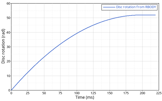
Figure 3. Rotation of the Brake Disc
As shown in Figure 3, the disc rotates 8.28 times around before stopping. The disc stops at t = 207.5 ms, which is 3% less than the analytical solution.

fig_23-6
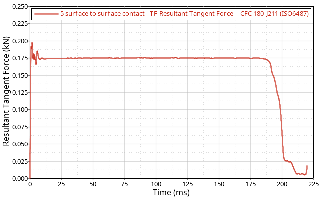
Figure 4. Resultant Tangent Force Filtered at 180 Hz
The reaction force value is filtered with an SAE J211/1 ISO6487 padding filter by using the iso6487 filter function in HyperGraph. The filtered resultant tangent force shown in Figure 4 is 0.175 kN, which is 3% less than the analytical solution.

fig_23-7
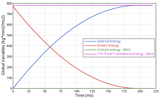
Figure 5. Energy Balance Plot

The total energy in the simulation remains constant. The initial kinetic energy is correctly converted into internal energy at the end of the simulation. Contact energy is numerical only and not physical so it should be a small value in the simulation.

Conclusion

The heat generated by contact friction is converted into internal energy and transferred to the disc. The contact force and rotation from the simulation match the analytical results.