RD-E: 1500 Gears

The purpose of this study is to demonstrate the use of quadratic interface contact using two gears in contact with identical pitch diameter and straight teeth. Two different contact interfaces are compared.
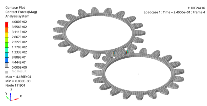
For mesh 20 node brick and 16 node shell element formulations are used to represent the curvature of the teeth. Constant velocity is applied to one gear. Initial rotational velocity around each center axis is used for both gears. The driven gear contains a torsional spring to provide resistance to the movement.

rad_ex_15_gears
Figure 1.

Options and Keywords Used

/BCS
Defines boundary conditions on node groups for translational and rotational motion.
/BRICK20
Describes 3D solid elements (20 node brick elements).
/IMPVEL
Defines imposed velocities on a group of nodes.
/INIVEL/AXIS
Initialize both translational and rotational velocities on a group of nodes in a given coordinate system.
/INTER/TYPE16
Simulates the impact between nodes and external surfaces of brick.
/INTER/TYPE17
Simulates the impact between external surfaces of two brick groups.
/SHEL16
Describes the 3D shell elements (16 node thick shell elements).
Note: The /SHEL16 elements are not supported by HyperMesh. Use HyperCrash to review the input file.

Input Files

The input files used in this example include:

<install_directory>/hwsolvers/demos/radioss/example/15_Gears/*

Model Description

The gear system is turning with a constant acceleration ( γ = 2.0e-6 rad/ms2).

The acceleration is applied to one gear. It is assumed that the contact between the teeth does not generate any friction.

Steel characteristic (elastic /MAT/LAW2) are:
Material Properties
Value
Young's Modulus
210000 [ MPa ] MathType@MTEF@5@5@+= feaagKart1ev2aqatCvAUfeBSjuyZL2yd9gzLbvyNv2CaerbuLwBLn hiov2DGi1BTfMBaeXatLxBI9gBaerbd9wDYLwzYbItLDharqqtubsr 4rNCHbGeaGqiVu0Je9sqqrpepC0xbbL8F4rqGqFfpeea0xe9vq=Jb9 vqpeea0xd9q8qiYRWxGi6xij=hbba9q8aq0=yq=He9q8qiLsFr0=vr 0=vr0db8meaabaqaciGacaGaaeqabaWaaeaaeaaakeaadaWadaqaai Gac2eacaGGqbGaaiyyaaGaay5waiaaw2faaaaa@3BE6@
Density
7.8x10-03 g/mm3
Poisson's ratio
0.29
Number of teeth
Z =19
Diametric pitch
P = 1/mo= 1/40
Pressure angle
ao= 20 degrees
The following parameters are calculated as:
Parameters
Value
Pitch diameter
Dp = mo* Z, then Dp = 760 mm
Root diameter
Db = mo* cos(ao), then Db = 714.17 mm
Addendum
ha = mo, then ha = 40 mm
Dedendum
hf = 1.25 * mo, then hf = 50 mm
Circular pitch
p = PI * mo, then p = 125.66 mm

rad_ex_fig_15-1
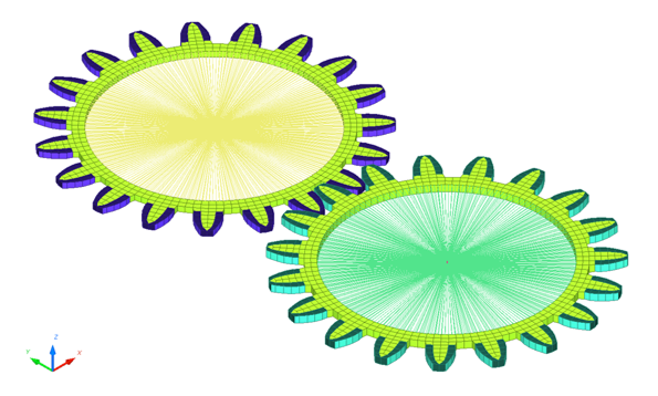
Figure 2. Global View of the Mesh
To apply constant acceleration, start at the time, t MathType@MTEF@5@5@+= feaagKart1ev2aaatCvAUfeBSjuyZL2yd9gzLbvyNv2CaerbuLwBLn hiov2DGi1BTfMBaeXatLxBI9gBaerbd9wDYLwzYbItLDharqqtubsr 4rNCHbGeaGqiVu0Je9sqqrpepC0xbbL8F4rqqrFfpeea0xe9Lq=Jc9 vqaqpepm0xbba9pwe9Q8fs0=yqaqpepae9pg0FirpepeKkFr0xfr=x fr=xb9adbaqaaeGaciGaaiaabeqaamaabaabaaGcbaGaamiDaaaa@36EF@ , with an initial rotation velocity around the individual axis to reduce the initial inertia effects. In addition, an imposed velocity is applied to one gear to which results in a rotational acceleration of 2.0E-6 rad/ms2. A spring is used to create a constant resistance momentum is applied to the rigid body of the second gear.


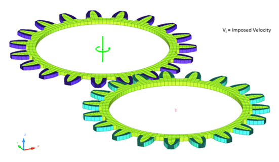
Figure 3. Imposed Velocity on the Rigid Body Main Node
The gears are modeled using 16 node thick shell elements (/SHEL16) and 20 node brick elements (/BRICK20). A quadratic solid mesh is used to represent the teeth’s curvature. The contact interfaces TYPE16 and TYPE17 are used to manage the contact between the quadratic surfaces of the 16 node thick shell elements.

rad_ex_fig_15-2
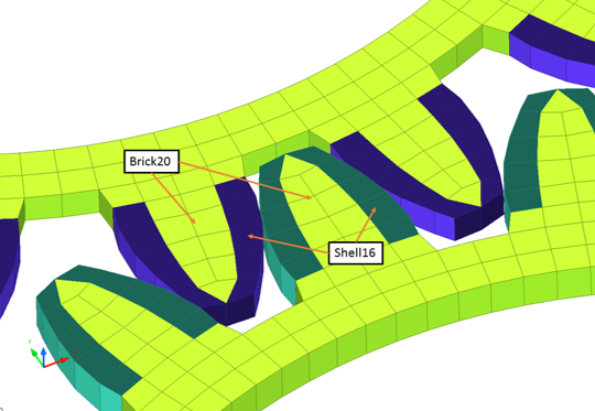
Figure 4. View of the Teeth
The contact interface TYPE16 and TYPE17 uses Lagrange Multiplier kinematical conditions. These kinematical conditions are only compatible with other Lagrange Multipliers kinematical conditions. This interface formulation is not compatible with the SPMD parallel version. Due to this limitation, these contact interfaces are not useful in large simulations that require many CPUs. The /INTER/LAGMUL/TYPE16 interface simulates the impact between nodes and external surfaces of brick. The external surfaces can be 16-node thick shell element, 20-node brick element, 8-node brick or 8-node thick shell element. The /INTER/LAGMUL/TYPE17 interface simulates the impact between the external surfaces of two brick groups. The external surfaces can only be 16-node thick shell (/SHEL16) elements. Lagrange Multiplier conditions are used in this interface.

rad_ex_fig_15-3
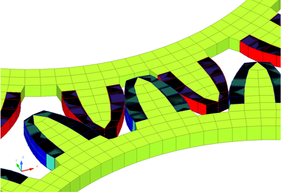
Figure 5. Contact Modeling between Quadratic Surfaces (TYPE 16/17 Interfaces)

Results

Time History Results

Figure 6 shows the application of velocities on the gears.

rad_ex_fig_15-6
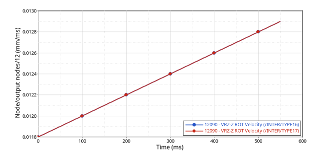
Figure 6. Imposed Rotational Velocity Curves

Conclusion

Both interfaces provide overall satisfactory results for this kind of application where the contact surfaces are complex and there is no gap. Since these contacts use Lagrange multiplier kinematical conditions, they only work with SMP parallelization which is limited to fewer CPUs compared to Hybrid and SPMD parallelization. For larger models, penalty contacts TYPE24 and TYPE25 work better for solid elements with no contact gap.