RD-E: 4200 Rubber Ring: Crush and Slide
A rubber ring resting on a flat rigid surface is pushed down by a circular roller to produce self-contact on the inside surface of the ring. Then the roller is simultaneously rolled and translated so that crushed ring rolls along the flat surface.
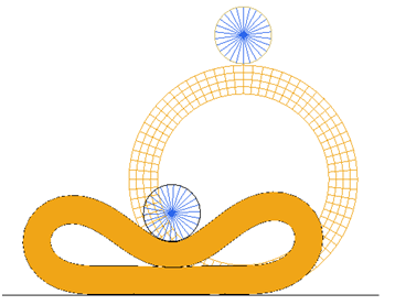
Figure 1.
This example is considered a static problem and the nonlinear implicit solver is used.
Options and Keywords Used
- Nonlinear implicit large displacement analysis
- Self-contact
- Hyper-elastic material
- Hyper-elastic rubber material (/MAT/LAW42 (OGDEN))
- Boundary conditions (/BCS)
- Releasing of dof (/BCSR)
- Imposed displacement (/IMPDISP)
- Incompressible solid element (/PROP/TYPE14 (SOLID))
- Contact definition (/INTER/TYPE7)
- Implicit analysis (Implicit Controls)
- Nonlinear Implicit Parameters
- Implicit type
- Static nonlinear
- Nonlinear solver
- BFGS Quasi-Newton method
- Termination criteria
- Relative residual in energy
- Tolerance
- 0.001
- Update of stiffness matrix
- 5 iterations maximum
- Time step control method
- Arc-length
- Initial time step
- 0.001
- Minimum time step
- 1e-6
- Maximum time step
- 0.001
- Line search method
- AUTO
- Special residual force computation with contact interfaces present
- 5
- Desired convergence iteration number
- 6
- Maximum convergence iteration number
- 15
- Decreasing time step factor
- 0.8
- Maximum increasing time step scale factor
- 1.1
- Arc-length
- Automatic computation
- Spring-back option
- No
- Linear Implicit Options
- Linear solver
- Direct
- Precondition methods
- Factored approximate Inverse
- Maximum iterations number
- System dimension (NDOF)
- Stop criteria
- Relative residual of preconditioned matrix
- Tolerance for stop criteria
- Machine precision
A restart analysis is performed for the second load step.
/IMPL/PRINT/NONLIN/-1 --- Printout frequency for nonlinear iteration
/IMPL/NONLIN/2 ---- Static nonlinear computation
 5 1 0.001
/IMPL/SOLVER/3 ----- Solver method (solve Ax=b)
5 0 3 0.0
/IMPL/DTINI ----- Initial time step determines initial loading increment
0.001
/IMPL/DT/STOP ------- Min Max values for time step
 1e-6 0.001
/IMPL/DT/2 ------ Time step control method 2 - Arc-length + Line-search will be used with this method to accelerate and control convergence.
 6 0 15 0.8 1.1
/IMPL/AUTOSPC/ALL ---- Constraining automatically zero stiffness dof
/IMPL/LSEARCH/3 ---- Line search method for nonlinear analysis
/IMPL/RREF/INTER/5 ------ Special Reference residual computation with contact
Refer to the Radioss manual for more details about implicit options.
Input Files
- Rubber_ring
- <install_directory>/hwsolvers/demos/radioss/example/42_Rubber_ring/rubber_ring*
Model Description
The purpose of this example is to demonstrate a nonlinear large displacement implicit analysis involving hyper-elastic material and contacts using Radioss.
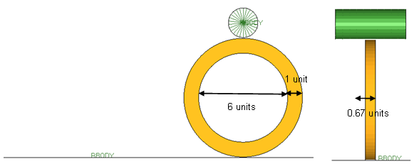
Figure 2. Geometry of the Rubber Ring and Roller Model
- Material Properties
- 0.7
- -0.5
- 2.0
- 2.0
- Poisson's ratio
- 0.495
- Material Properties
- Density
- 7.9e-9
- Young's modulus
- 600
- Poisson's ratio
- 0.3
Geometric Linear (NLSTAT) or Geometric Nonlinear (NLGEOM) Analysis
In geometric linear analysis all deformations and rotations are small - displacements of 5% of the model dimension are considered small.
For this rubber ring example, the final deformations and strains after crushing the rubber ring are much larger than the above mentioned limit. So, the geometrically linear static NLSTAT analysis could not be considered for this example.
Model Method
- Mesh and propertiesThe ring mesh is a regular solid mesh modeled with four elements (dimension of 0.25 units) along the width and two elements (dimension of 0.335 units) through the thickness. The flat rigid surface and the circular roller are both modeled as a regular shell mesh of 0.01mm thickness with the flat surface around 0.75 units in dimension and the roller being around 0.467 units in dimension.
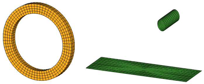
Figure 3. Geometry of the Rubber Ring and Roller ModelThe ring has been modeled using first order fully-integrated solid elements./PROP/SOLID/5 WHEEL 14 10 1 222The flat surface and roller have been modeled using the first order reduced integration shell elements with three integration points through the thickness. Full integration elements were not considered as you are not interested in any detailed post-processing of the barrier./PROP/SHELL/6 BARRIER 1 2 3 0.01 - Load and boundary conditionsThe boundary conditions applied to the rubber ring in step 1 are shown in Figure 4.
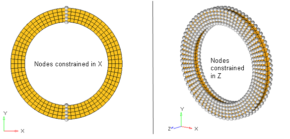
Figure 4. Boundary Conditions Applied to Ring in First StepThe boundary conditions applied to the flat rigid surface and circular roller in step 1, are shown in Figure 5.
The flat surface is constrained in all DOF's, while the roller is pushed down by 6.22 units in Y-axis so much that self-contact is established within the inner surface of the ring.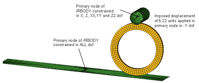
Figure 5. Boundary Conditions Applied to Flat Surface and Roller in 1st StepIn the second step, the top roller is to be simultaneously translated and rotated such that the wheel in the crushed configuration rolls along the flat rigid surface in -X direction. So, the X translation and ZZ rotations of the circular roller have to be released from the primary node of /RBODY. Additionally, the center nodes of the ring that were constrained in X DOF (Figure 4) need to be released for the ring to roll along the flat surface. So, the Engine file for the second step has the following cards representing release of the above-mentioned degrees of freedom./BCSR/TRA/X/ 5 6 8 9 15 16 17 18 87 88 89 93 94 95 241 242 243 244 245 246 5717 5699 5681 5663 5662 5537 5517 5497 5477 5476 2269 /BCSR/ROT/Z 2269 - Contact definition
Several contacts have been defined: i) contact between the circular roller and rubber ring, (ii) contact between the flat rigid surface and rubber ring, and (iii) self-contact within the inner surface of the rubber ring.
A small physical gap (0.05 units) has been introduced between the circular roller and the rubber ring and also between rubber ring and the flat rigid surface. The minimum gap specified for the contact is slightly higher than the physical gap for contact to take effect. Static Coulomb friction of 0.5 is defined for all the interfaces. The definition of one such interface is:/INTER/TYPE7/14 TOP_Rubber 25 30 4 0 0.5 0.055 000 0 0 2Also, since the contact involved is between a rigid part and a very soft hyper-elastic material, it is advisable that the E*h (Young's modulus * thickness) of the rigid part be approximately the same order as the bulk modulus of the rubber material.
Results
Animations
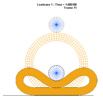
Figure 6. Deformed Shape of the Rubber Ring After 1st Step
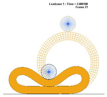
Figure 7. Deformed Shape of the Rubber Ring After 2nd Step
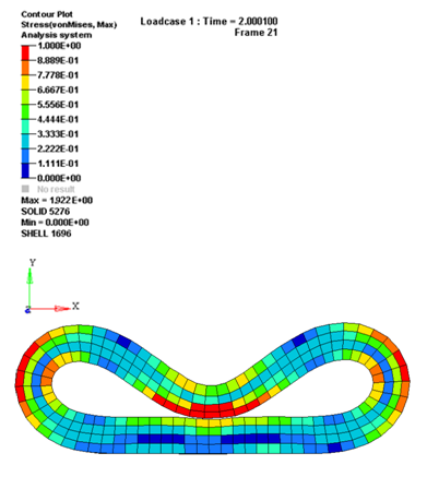
Figure 8. Stress in the Rubber Ring