RD-E: 0700 Pendulums

The purpose of this example is to study the energy propagation and the momentum transfer through several bodies, initially in contact with each other, subjected to multiple impact. The process of collision and the energetic behavior upon impact are described using a 3-dimensional mode.
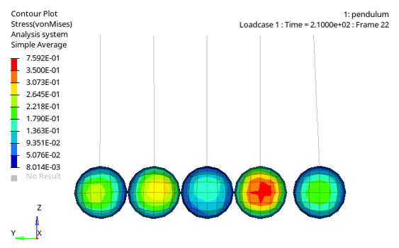

pendulums
Figure 1.

This example simulates the oscillation and wave propagation of a group of pendulums in a line when impacted at one end. The material is elastic. The quality of the model first depends on how the contact is managed. For this model a TYPE24 contact interface using penalty method is used.

Options and Keywords Used

  • 3-dimensional analysis, truss (thread), brick and brick (hexahedron elements)
  • /INTER/TYPE2
  • /INTER/TYPE14
  • General nodes-to-surface contact interface using the penalty method (/INTER/TYPE24)
  • Elasticity, momentum transmission, shock wave propagation, multiple impacts.
  • Gravity (/GRAV)
  • Boundary conditions on node groups for translational and rotational motion (/BCS)

Input Files

The input files used in this example include:

<install_directory>/hwsolvers/demos/radioss/example/07_Pendulums/

Model Description

Five pendulums in line, initially in contact with each other, are struck by a sixth one. The shock wave and oscillating motion are observed.

Units: g, ms, mm, MPa

A metal ball strikes a line of four balls, initially in contact with each other (Figure 2). The momentum is transferred from pendulum to pendulum until reaching the last one at the opposite end. The system is subjected to gravity.


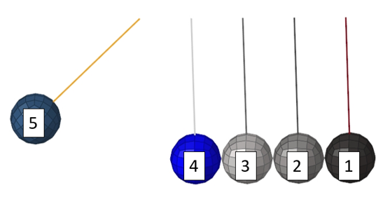
Figure 2. 3-dimensional Mesh in Initial State
The left pendulum has an initial angle of 45° in relation to the vertical. The material used is aluminum alloy which behaves like a linear elastic law (/MAT/LAW1 (ELAST)) during impact and has the following characteristics.
Properties
Young's modulus
70000 [ MPa ] MathType@MTEF@5@5@+= feaagKart1ev2aqatCvAUfeBSjuyZL2yd9gzLbvyNv2CaerbuLwBLn hiov2DGi1BTfMBaeXatLxBI9gBaerbd9wDYLwzYbItLDharqqtubsr 4rNCHbGeaGqiVu0Je9sqqrpepC0xbbL8F4rqGqFfpeea0xe9vq=Jb9 vqpeea0xd9q8qiYRWxGi6xij=hbba9q8aq0=yq=He9q8qiLsFr0=vr 0=vr0db8meaabaqaciGacaGaaeqabaWaaeaaeaaakeaadaWadaqaai Gac2eacaGGqbGaaiyyaaGaay5waiaaw2faaaaa@3BE6@
Poisson's ratio
0.33
Density
0.0027 [ g m m 3 ] MathType@MTEF@5@5@+= feaagKart1ev2aaatCvAUfeBSjuyZL2yd9gzLbvyNv2CaerbuLwBLn hiov2DGi1BTfMBaeXatLxBI9gBaerbd9wDYLwzYbItLDharqqtubsr 4rNCHbGeaGqiVu0Je9sqqrpepC0xbbL8F4rqqrFfpeea0xe9Lq=Jc9 vqaqpepm0xbba9pwe9Q8fs0=yqaqpepae9pg0FirpepeKkFr0xfr=x fr=xb9adbaqaaeGaciGaaiaabeqaamaabaabaaGcbaWaamWaaeaada WcaaqaaiaadEgaaeaacaWGTbGaamyBamaaCaaaleqabaGaaG4maaaa aaaakiaawUfacaGLDbaaaaa@3BBC@
The geometrical characteristics:
Truss
Length
124.6 mm
Ball
Radius
25.4 mm
Mass
169.7 g

A TYPE24 contact interface uses a penalty method with a linear contact stiffness to model the contact between the balls. A self-contact definition between all the balls is used to model the contact between the nodes and the element surface. Interfaces using the penalty method are based on main/secondary treatment.

Brick elements are used to model the balls. No contact gap is required for the TYPE24 interface.

Gravity is applied to all nodes. A gravity versus time function is applied to define the gravity acceleration in the Z direction. Gravity is activated by the /GRAV option.

The top of the trusses are fixed in X, Y and Z translations and in Y and Z rotations (free in X rotation).

Results

When considering the kinetic energy variation of the model, the system behaves as a simple pendulum (Figure 3).

When the pendulum mass is released at time t=0, Ball 5 (end ball) has maximum potential energy and zero kinetic energy. Ball 5 achieves maximum velocity before striking the four other pendulums. For a moderate case that is without loss, you have:(1) E p o t = E k i n m g h = 1 2 m v 2 MathType@MTEF@5@5@+= feaagKart1ev2aaatCvAUfeBSjuyZL2yd9gzLbvyNv2CaerbuLwBLn hiov2DGi1BTfMBaeXatLxBI9gBaerbd9wDYLwzYbItLDharqqtubsr 4rNCHbGeaGqiVu0Je9sqqrpepC0xbbL8F4rqqrFfpeea0xe9Lq=Jc9 vqaqpepm0xbba9pwe9Q8fs0=yqaqpepae9pg0FirpepeKkFr0xfr=x fr=xb9adbaqaaeGaciGaaiaabeqaamaabaabaaGceaqabeaacaWGfb WaaSbaaSqaaiaadchacaWGVbGaamiDaaqabaGccqGH9aqpcaWGfbWa aSbaaSqaaiaadUgacaWGPbGaamOBaaqabaaakeaacaWGTbGaam4zai aadIgacqGH9aqpdaWcaaqaaiaaigdaaeaacaaIYaaaaiaad2gacaWG 2bWaaWbaaSqabeaacaaIYaaaaaaaaa@46E4@
Where,
h MathType@MTEF@5@5@+= feaagKart1ev2aaatCvAUfeBSjuyZL2yd9gzLbvyNv2CaerbuLwBLn hiov2DGi1BTfMBaeXatLxBI9gBaerbd9wDYLwzYbItLDharqqtubsr 4rNCHbGeaGqiVu0Je9sqqrpepC0xbbL8F4rqqrFfpeea0xe9Lq=Jc9 vqaqpepm0xbba9pwe9Q8fs0=yqaqpepae9pg0FirpepeKkFr0xfr=x fr=xb9adbaqaaeGaciGaaiaabeqaamaabaabaaGcbaGaamiAaaaa@36E3@
Vertical displacement of the ball’s center
v MathType@MTEF@5@5@+= feaagKart1ev2aaatCvAUfeBSjuyZL2yd9gzLbvyNv2CaerbuLwBLn hiov2DGi1BTfMBaeXatLxBI9gBaerbd9wDYLwzYbItLDharqqtubsr 4rNCHbGeaGqiVu0Je9sqqrpepC0xbbL8F4rqqrFfpeea0xe9Lq=Jc9 vqaqpepm0xbba9pwe9Q8fs0=yqaqpepae9pg0FirpepeKkFr0xfr=x fr=xb9adbaqaaeGaciGaaiaabeqaamaabaabaaGcbaGaamODaaaa@36F1@
Velocity
m MathType@MTEF@5@5@+= feaagKart1ev2aaatCvAUfeBSjuyZL2yd9gzLbvyNv2CaerbuLwBLn hiov2DGi1BTfMBaeXatLxBI9gBaerbd9wDYLwzYbItLDharqqtubsr 4rNCHbGeaGqiVu0Je9sqqrpepC0xbbL8F4rqqrFfpeea0xe9Lq=Jc9 vqaqpepm0xbba9pwe9Q8fs0=yqaqpepae9pg0FirpepeKkFr0xfr=x fr=xb9adbaqaaeGaciGaaiaabeqaamaabaabaaGcbaGaamyBaaaa@36E8@
Mass
Using the formulas (Equation 1), analytical potentital energy in the system is 73.1365 mJ.


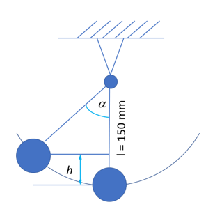
Figure 3. Pendulum Motion
The two extreme pendulums alternate oscillating for half of the time period.


Figure 4. Kinetic Energy Transfer between Ball 5 and Ball 1
In Figure 4, a reduction of kinetic energy between pendulum balls due to contact damping can be observed. The kinetic energy in the system is not entirely maintained due to the energy contact being dissipated during impact. The maximum kinetic energy of Ball 5 just prior to contact with the other balls is 73.135 mJ. This is very close to the analytical energy of 73.136 mJ. When the kinetic energy is transferred from Ball 1 back to Ball 5 at 612.5 ms, the kinetic energy in Ball 5 is 69.187 mJ.


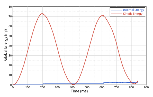
Figure 5. Global Internal and Kinetic Energy
Plotting the global energy of the system in Figure 5 shows that some of the potential energy is converted into internal energy in the system.


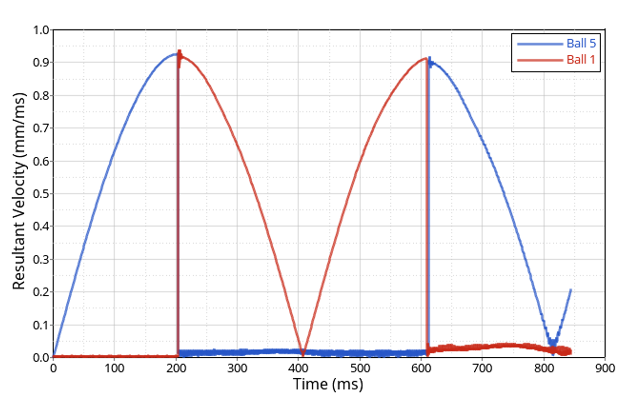
Figure 6. Velocity Curve of Ball 5 and Ball 1

Conclusion

The oscillation and wave propagation of a group of pendulums, arranged in a line was studied using Radioss. The model has a coarse mesh with 3D elements to reduce the computation time. The contact was modeled with /INTER/TYPE24 using penalty method. Results were compared to an analytical solution where the pendulum system is assimilated to a simple pendulum. The results obtained by simulation and theory demonstrate the validity of the numerical results obtained by Radioss.