RD-E: 4400 Blow Molding with AMS
Blow molding with Advanced Mass Scaling (AMS).
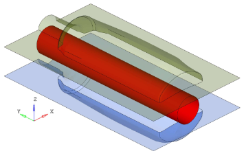
Figure 1.
Options and Keywords Used
- Advanced Mass Scaling (/AMS)
- Time Step for Advanced Mass Scaling (/DT/AMS/Iflag)
- TYPE7 interface (/INTER/TYPE7)
TYPE7 interface has been defined between mold and plastic parison with friction 0.7.
- Visco Elastic Plastic Piecewise Linear Material law (/MAT/LAW66)
- Shell property (/PROP/TYPE1 (SHELL))
- Rayleigh damping (/DAMP)
- Rigid body (/RBODY) and Boundary condition
(/BCS)
Using rigid body, two molds have been fixed in all direction of rotation and translations of y-direction and x-direction. They are only free in z-direction (translation).
- Impose displacement (/IMPDISP)
Two molds are moved in opposite directions with imposed displacement.
- Pressure Load (/PLOAD)The air pressure on the plastic parison is modeled using pressure load /PLOAD from inside towards outside.
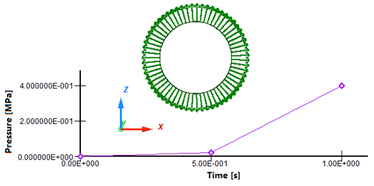
Figure 2. Pressure Load on Plastic Parison
Input Files
- Example 44
- <install_directory>/hwsolvers/demos/radioss/example/44_blow_molding_ams/E4_66_AMS/*
Model Description
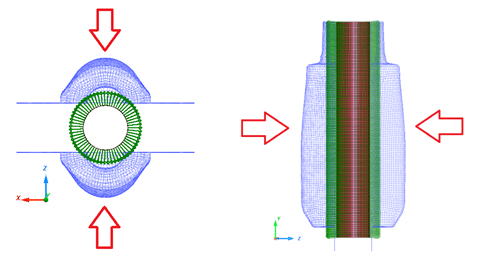
Figure 3. Problem Description for Blow Molding
Units: mm, s, Mg , N , MPa
- Material Properties
- Initial density
- 7.8e-9 Mg/mm3
- Young's modulus
- 200000
- Poisson's ratio
- 0.3
- Material Properties
- Initial density
- 1e-9 Mg/mm3
- Young's modulus
- 4
Model Method
- Define /AMS in Starter. Select the part group which will use AMS. If the part group has not been specified, then the whole model will use AMS.
- Use /DT/AMS in Engine. For
example:
/DT/AMS
0.67 1.15e-4
Results
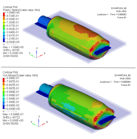
Figure 4. Plastic Strain and von Mises Stress on Plastic Parison
Performance
Using the AMS technique, CPU time is reduced by a factor of approximately 3, in this case.
- Without time step control (no mass scaling)
- With standard mass scaling /DT/NODE/CST
- With AMS
| Without Time Step Control | With Standard Mass Scaling /DT/NODA/CST | With AMS | |
|---|---|---|---|
| Time Step(s) | 1.15e-4 | 0.34e-04 | 1.15e-4 |
| Total Number of Cycle | 78200 | 24280 | 6966 |
| CPU Time(s) | 2027.82 | 723.02 | 522.83 |
| Speed-up | - | 2.80 | 3.88 |
| Results Quality | - | Bad | Good |
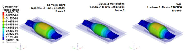
Figure 5. Plastic Strain for Tests Without Time Step Control (no mass scaling). With /DT/NODA/CST and With AMS at Time 0.4s.
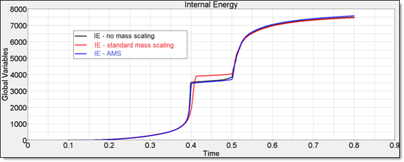
Figure 6. Internal Energy on Plastic Parison With and Without AMS
It shows at time 0.4s for the same speed up factor with AMS you get more accurate results compare with no mass scaling test than with node mass scaling.
Conclusion
To obtain a CPU saving factor of about 3, the target time step should be about 10 times higher than the one without AMS; AMS treatment itself is taking some CPU cost.
Standard mass scaling technique can also speed up the calculation by a factor of about 3, but the results quality will be affected.
In general, AMS technique for a given speed up, gives more accurate results than standard mass scaling.
The AMS technique does not change the total mass; the mass is added only on non-diagonal terms of the mass matrix.
It is applicable to the entire model.
- Result accuracy, in terms of stress and strains, is normally not affected; by the way AMS is affecting Eigen modes of the structure(s) to which it is applied. Higher frequencies are lowered.
- AMS technique is highly scalable; large models could show even more significant speed up factors.