RD-E: 0100 Twisted Beam Example
Bending test on a twisted beam modeled with triangular and quadrilateral meshes and different element formulations (QEPH, QBAT, DKT18).
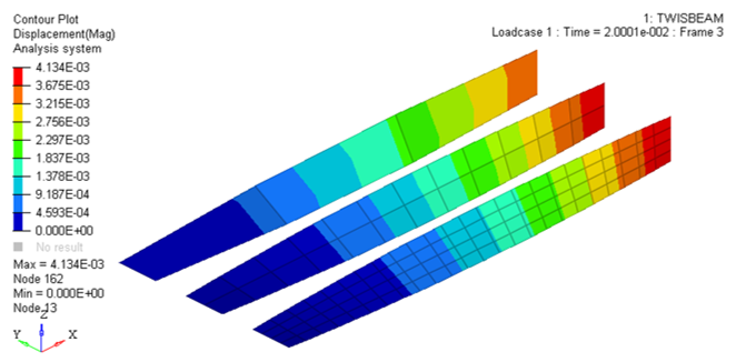
Figure 1.
The subject of this example is the comparison and validation of different shell elements (4-node shell and 3-node shell) regarding their mesh quality (mesh density), sensitivity and cost. Shell elements are very popular in finite element computations of shell structures. A full car crash model is made of at least 90% shell elements. Shells include membrane, bending and shear deformation. The through the thickness normal stress is always zero. Meshes for low order elements can be easily generated. As a numerical example, a beam modeled of shell elements is used, which is clamped on the left side and exposed on the right side of a coupled torsional bending load. The simulation results are compared with each other and validated by an analytical solution.
The problem of analysis consists of a concentrated load being applied to the end of the beam with the static approach requiring a convergence method to enable fast convergence towards equilibrium. The dynamic relaxation option allows for an efficient quasi-static response to be obtained.
- Shell element formulations (BATOZ, QEPH, and DKT18).
- Influence of the mesh (Triangular and quadrilateral meshes are compared using three different element densities: 4x24, 2x12 and 1x3).
- X-displacement of the loaded point
- Y-displacement of the loaded point
- Z-displacement of the loaded point
- Error on energy
- CPU time
Comparisons are made between theoretical displacements and those by simulations.
Results show that QEPH and BATOZ element formulations provide the most accurate results and the smaller the mesh size, the more accurate the results will be. To pass this test, a good curvature representation of element formulation is needed; the BT hourglass type 4 formulation does not satisfy this condition. QEPH offers a good ratio in terms of precision-cost, and is useful for quasi-static analysis. DKT18 is a costly element formulation.
Options and Keywords Used
- /PROP/TYPE1 (SHELL), Ishell= 4-node shell (Q4) and 3-node shell (T3)
- QEPH, QBAT and DKT18
- Density mesh and elasticity
- Linear problem
- Concentrated load (/CLOAD)
- Dynamic relaxation (/DYREL)
Input Files
- QEPH
- <install_directory>/hwsolvers/demos/radioss/example/01_Twisted_Beam/QEPH/TWISBEAM*
- QBAT
- <install_directory>/hwsolvers/demos/radioss/example/01_Twisted_Beam/BATOZ/TWISBEAM*
- DKT18
- <install_directory>/hwsolvers/demos/radioss/example/01_Twisted_Beam/DKT18/TWISBEAM*
Model Description
The purpose of this example is to compare element formulations concerning mesh density with respect to a coupled torsion-bending problem.
Units: in, s, slinch, lbf, psi
A twisted beam is clamped at one end, and subjected to a concentrated load at the other end.
- Material Properties
- Initial density
- Young's modulus
- 2.9x10⁷ psi
- Poisson ratio
- 0.22
- Thickness
- 0.32 in
- Length
- 12 in
- Width
- 1.1 in
- Load case
- Fy = 1.0 lbf
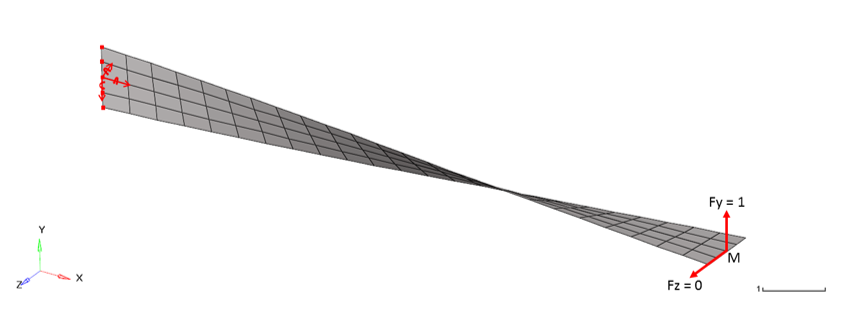
Figure 2. Initial Mesh (4x24)
This simple test is particularly severe for shell element formulations, due to the torsion-bending coupling that is caused by the twisted or warped elements.
- Displacements are very low. Thus, you are faced with a linear problem.
- Another load case, using Fy = 0 and Fz = 1 lbf, is considered, but does not give concern to additional conclusions.
Since the load is applied in quickly, dynamic relaxation is used to obtain a static result. Using /DYREL in the *_0002.rad file, the dynamic loading is damped by introducing a diagonal damping matrix.
Relaxation factor = 1, period to be damed = 0.0025
The displacement of node M is stabilized at the static response, t = 0.035.
Simulation Iterations
The beam is modeled with 4-node shell and 3-node shell meshes.
- Three shell formulations:
- QEPH formulation (4-node shell element, Ishell= 24)
- QBAT formulation (4-node shell element, Ishell= 12)
- DKT18 formulation (3-node shell element, Ish3n= 30)
- Three mesh densities in each shell formulation:
- Mesh A: 4 x 24 elements
- Mesh B: 2 x 12 elements
- Mesh C: 1 x 3 elements
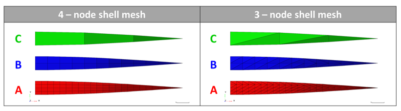
Figure 3. Overview Mesh (4-node shell mesh and 3-node shell mesh)
Results
- Theoretical Results
- X-displacement
- = 0 in
- Y-displacement
- = 0.00175 in
- Z-displacement
- = -0.00179 in
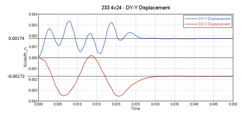
Figure 4. Time History Plots of Point M Displacements (Mesh A/QEPH)
- Energy Error at t = 0.05:
- QEPH
- 0.1%
- BATOZ
- 0%
- DKT18
- 0%
- CPU (normalized):
- QEPH
- 1
- BATOZ
- 1.69
- DKT18
- 1.58
- Ratio (Displacement by Simulation/Displacement of Theory):
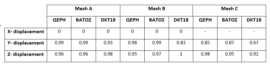
Conclusion
- QBAT and QEPH provide good results compared to theory.
- DKT18 provides acceptable results, if the mesh is fine.
- QEPH is the best element formulation. Very good precision-cost ratio.
- QBAT has good curvature representation. The cost is 4% higher compared to using the QEPH formulation.
- DKT18: For quasi-static analysis, the cost is about 60% higher compared to using the QEPH formulation.