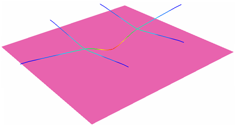
A beam frame receives an impact from a mass having initial velocity.
A beam frame with clamped extremities receives an impact at its mid-point from a pointed mass
having initial velocity. The material is subjected to the elasto-plastic law of
Johnson-Cook. The model is meshed with beam elements. An infinite rigid wall with
only one secondary node, including the impacted node, is subjected to the initial
velocity. This example is considered a dynamic problem and the explicit solver is
used. Figure 1.
The explicit approach leads to finding a quasi-static equilibrium of the structure after impact.
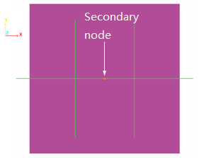
The impacting mass is simulated using a sliding rigid plane wall
(/RWALL) having an initial velocity of 10 ms-1and
a mass of 3000 g. Only one secondary node exists: the node O to simulate a point
impact.
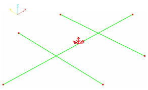
Points A, F, F', D, E and E' are fully fixed. Figure 2. Boundary Conditions Figure 3. Rigid Wall Type Infinite Plane
The purpose of this example is to perform a static analysis using beam
elements.
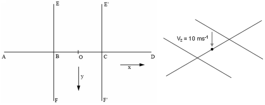
A pointed mass (3 kg) makes an impact at point O of a beam frame (see Figure 4 for the geometry) using a speed of 10
ms-1in the Z direction. The beams are made of steel and each beam
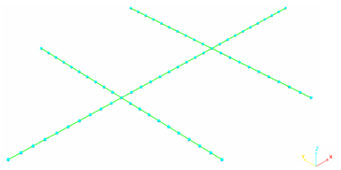
section is square-shaped (each side being 6 mm long). Figure 4. Geometry of the Frame
Dimensions are: AB = BC = CD = BE = BF = E'C = CF' = 90 mm.
Points A, D, E, F, E', and F' are fixed.
Beam Properties
Cross section
36 mm2
Moments of inertia in Y and Z
108 mm4
Moments of inertia in X
216 mm4
The steel material used has the following properties:
Material Properties
Density
0.0078
Young's modulus
200 000
Poisson's ratio
0.3
Yield stress
320
Hardening parameter
134.65
Hardening exponent
1.0
All other coefficients are set to default values. Plasticity is taken into account using LAW2
without failure.
Model Method
The mesh is a regular beam mesh, each beam being 9 mm long (total = 70 beams). Figure 5. Mesh of the Frame Showing the Position of the Nodes
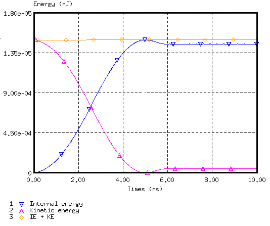
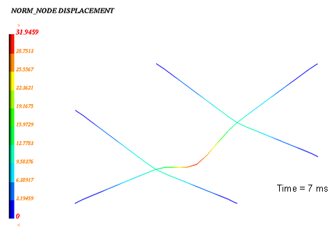
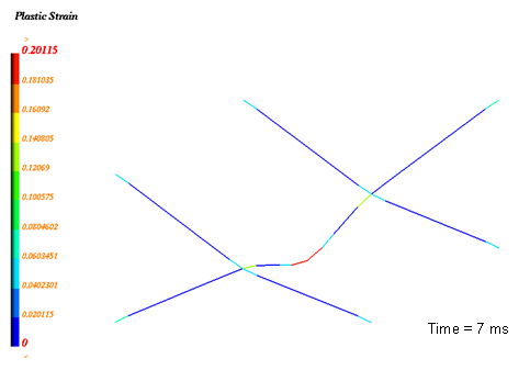
Results
Curves and Animations
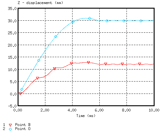
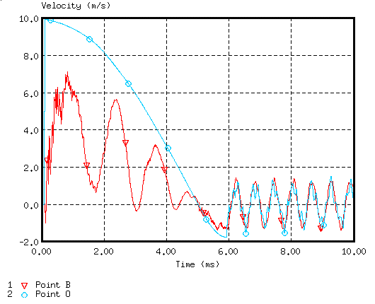
The main results refer to the time history of points B and O with regard to displacements and
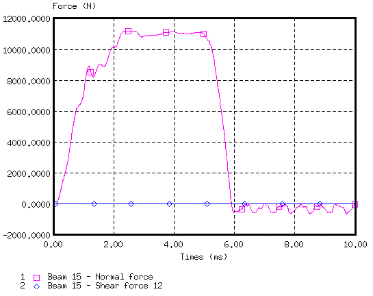
velocities. Figure 6. Displacements of Points B and O Figure 7. Velocity of Points B and O (stabilization) Figure 8. Normal and Shear Force on Beam Element 15 (near to point O) Figure 9. Energy Assessment (stability reached at in 6 ms) Figure 10. Node Displacement (max. = 30.96 mm) Figure 11. Plastic Strain (max. = 20.1%)