RD-E: 0401 Driver Airbag
Deployment of a folded multi-chambered uniform pressure airbag into a head impactor.
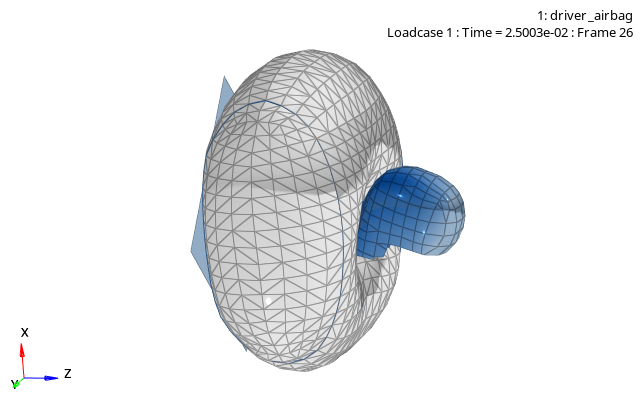
Figure 1. Deployed airbag with rigid head-form impactor
The accurate prediction of the overall deployment phases of airbags is crucial for passenger protection in motor vehicles. Due to its specific application airbags are modeled in different ways.
The subject of this example is to demonstrate the deployment process of a simple multi-chambered airbag hitting an impactor. The airbag is initially folded along four-fold-lines and is modeled by monitored volumes using communications between chambers. The modeling is based on a uniform pressure approach, where uniform pressure distribution in the entire control volume (chamber) is applied.
- Pressure inside of the airbag
- Airbag volume
- Mass of gas inside of the airbag
- Gas temperature
- Universal gas constant
The physical airbag with local pressure and gas velocity distribution, in each part of the bag, turns into a uniform pressure description, where the pressure and the temperature are constant in each chamber of the airbag. The gas generator will be represented by the load curves, which control the injected mass flow rate and gas temperature. Outflow takes place through vent holes or porous fabric ().
A more sophisticated method (Finite Volume Method: FVM) is the topic of another example.
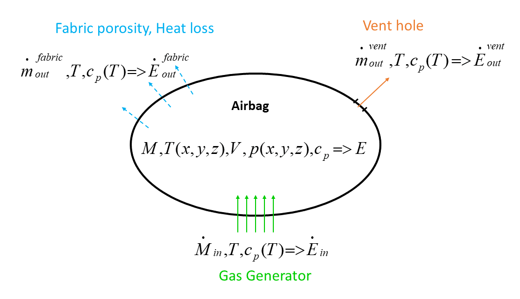
Figure 2. Overview of the uniform pressure airbag modeling method
Options and Keywords Used
Units used: Mg mm s
- /MAT/LAW19 (FABRI) (elastic orthotropic material for modeling airbag fabric)
- /MAT/GAS/MASS (Coefficients of Cp(T) per mass unit)
- /MAT/LAW0 (VOID) (Define elements to act as a void or an empty space)
- /PROP/TYPE9 (SH_ORTH) (Orthotropic property shell definition)
- /PROP/INJECT1 (Describes mass injected for each constituent gas)
- /PROP/TYPE4 (SPRING) (Spring property with one translational DOF)
- /PROP/TYPE1 (SHELL) (Shell property set)
- /INTER/TYPE19 (Airbag self-contact)
- /RWALL (Infinite rigid plane)
- /BCS (Fix inflator)
- /SENSOR (time sensor defining time to fire of the airbag)
- /DAMP (Rayleigh mass and stiffness damping coefficients, applied to a set of nodes)
- /MONVOL/COMMU1 (Airbag monitored volume communications)
Input Files
The input files used in this example include:
<install_directory>/hwsolvers/demos/radioss/example/04_Airbag/driver/*
Model Description
An approximately 80-liter airbag is folded along four fold lines.
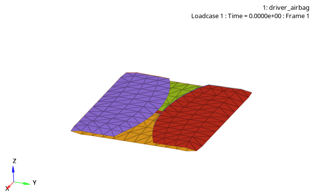
Figure 3. Structures overall mesh
- Material Properties
- Density
- 0.85 x 10⁻¹⁰
- Young's modulus
- 500 in both directions
- Shear modulus
- 10 (G12, G23, G31)
- Reduction factor
- 0.001
The property set is /PROP/SH_ORTH (shell orthotropic, TYPE9), with one integration point to neglect bending stiffness of fabric material. The default 3 node tria element formulation is used.
Model Method
- the fabric layers
- the communication surfaces
The fabric surface is then divided into 9 subsets, one for each monitored volume. Each "monitored volume" is further divided into two parts. All the parts of the layer of the fabric have the same property and mat_ID.
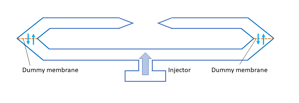
Figure 4. Folder Airbag with Communications
The airbag is modeled using 9 communicating volumes to simulate approximately propagation of air into the folds. The communicating surfaces between the volumes are simulated using dummy membranes (Figure 4). The dummy membranes are modeled using shells with void material (/MAT/LAW0 (VOID)).
A monitored volume of each airbag chamber is defined as a collection of surfaces. The volume should be closed, the normal of the shells is directed outwards. The monitored volume used, is a COMMU1 type for airbags, using communications (chambered, with communications, of the folded airbags). For further details about monitored volumes, refer to COMMU1 Type in the Radioss Theory Manual.
Gas materials are specified in separate /MAT/GAS cards (using MASS type), which describe the gas molecular weight MW and specific heat coefficients Cpa, Cpb, etc. in the polynomial function Cp(T).
For the property, of the injector /PROP/INJECT1 is used, which describes the mass injected for each constituent gas. The final injected mass is 47 g, injected into the central chamber ( and =1). Two functions define the mass and temperature of the injected gas controlled by time (function identifiers: and ).
- Properties
- Mu (Volumetric viscosity)
- 0.001 (default)
- Pext (External pressure)
- 0.1
- T0 (Initial temperature)
- 296.0
- Ittg (Timeshift flag)
- 3
- Njet (Number of injectors)
- 1
- Vent hole membrane surface area
- 1000 mm2 (Avent = 0) is immediately activated
- Communication area
- Total (Acom = 1 and Scom = 0)
Interface
- To model the airbag self-contact, the contact interface /INTER/TYPE19 is used. This contact combines surface to surface and edge to edge contact and uses surface input based on the same secondary/main surfaces. The interface's main and secondary surfaces are defined using /SURF/PART. If different contact parameters need to be used for the surface to surface contact and edge to edge contact, then this can be done by replacing the /INTER/TYPE19 contact with a /INTER/TYPE7 node to surface self-contact and a /INTER/TYPE11 edge contact.
- The distance between the fabric layers before unfolding is very small. To avoid initial penetration, Inacti=6 is used to automatically reduce the contact gap thickness. There should be no initial intersections in the contact at the beginning of the simulation.
- It is recommended to set Ibag=1 which stops venting through the airbag in areas where contact occurs.
- A constant contact thickness similar to the fabric thickness of Gapmin=0.3 is used.
Time Step Control
Nodal time step control /DT/NODA/CST is used in the model with a typical crash simulation time step. To improve model stability, a maximum time step is set using the /DTIX. This would normally not be needed since the time step in a crash simulation would normally be controlled by other parts in the simulation.
Impactor Head
The dummy head is modeled as a simplified head of a crash test dummy and modeled as a rigid part. The head is constrained to prevent rotation in all directions. It can only translate in the z-direction.
Results
Curves and Animations
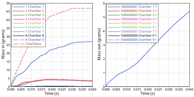
Figure 5. Monitored Volume - Mass
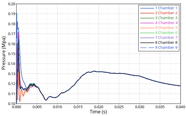
Figure 6. Monitored Volume - Pressure
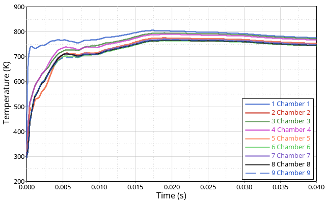
Figure 7. Monitored Volume - Temperature
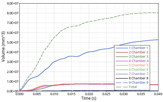
Figure 8. Monitored Volume - Final Volume of the Airbag
The final volume of the airbag after deploying is about 80 liters.
Animations
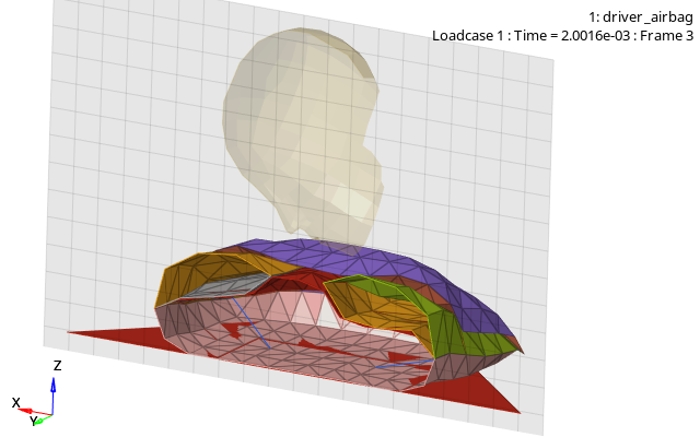
Figure 9. Central Chamber is Inflating
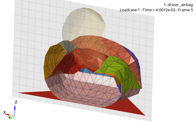
Figure 10. All Chambers are Inflating
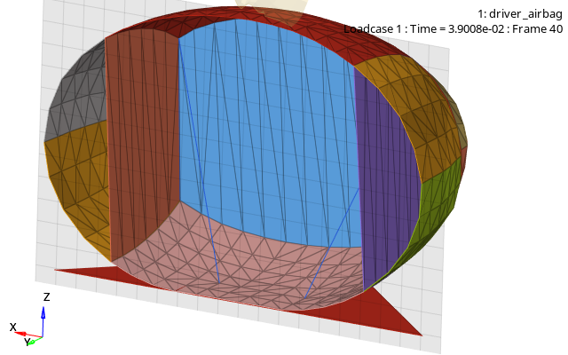
Figure 11. Airbag is Deployed