/INTER/TYPE19

Block Format Keyword This is a combination of two symmetric TYPE7 interfaces and one TYPE11 interface, with common input based on the same secondary/main surfaces. Secondary node group for interface TYPE7, as well as secondary and main line segments used by equivalent TYPE11 interface are virtually generated from these input surfaces.

Format

(1) (2) (3) (4) (5) (6) (7) (8) (9) (10)
/INTER/TYPE19/inter_ID/unit_ID
inter_title
surf_IDs surf_IDm Istf Ithe Igap Iedge Ibag Idel Icurv  
Fscalegap Gapmax            
Stmin Stmax %mesh_size dtmin Irem_gap Irem_i2
Insert if Icurv = 1 or 2
(1) (2) (3) (4) (5) (6) (7) (8) (9) (10)
node_ID1 node_ID2                
Required Fields
(1) (2) (3) (4) (5) (6) (7) (8) (9) (10)
Stfac Fric Gapmin Tstart Tstop
IBC     Inacti VISs VISF Bumult
Ifric Ifiltr Xfreq Iform sens_ID       fric_ID
Insert if Ifric > 0
(1) (2) (3) (4) (5) (6) (7) (8) (9) (10)
C1 C2 C3 C4 C5
Read this input only if Ifric > 1
(1) (2) (3) (4) (5) (6) (7) (8) (9) (10)
C6                
If Ithe = 1, read this input
(1) (2) (3) (4) (5) (6) (7) (8) (9) (10)
Kthe fct_IDK   Tint Ithe_form AscaleK  
Frad Drad Fheats Fheatm    

Definitions

Field Contents SI Unit Example
inter_ID Interface identifier.

(Integer, maximum 10 digits)

 
unit_ID Unit Identifier.

(Integer, maximum 10 digits)

 
inter_title Interface title.

(Character, maximum 100 characters)

 
surf_IDs Secondary surface identifier.

(Integer)

 
surf_IDm Main surface identifier.

(Integer)

 
Istf Stiffness definition flag. 8
= 0
Use value in /DEFAULT/INTER/TYPE19.
= 1
Interface stiffness is entered as Stfac.
= 2
Interface stiffness is the average of the main and secondary stiffness.
= 3
Interface stiffness is the maximum of the main and secondary stiffness.
= 4
Interface stiffness is the minimum of the main and secondary stiffness.
= 5
Interface stiffness is the main and secondary stiffness in series.
= 1000 Default, if /DEFAULT/INTER/TYPE19 is not defined.
For node to surface contact, interface stiffness is only based on main stiffness.
For edge to edge contact, interface stiffness is the main and secondary stiffness in series.

(Integer)

 
Ithe Heat contact flag. 25
= 0 (Default)
No heat transfer or heat friction.
= 1
Heat transfer or heat friction activated.

(Integer)

 
Igap Gap/element option flag. 6 7
= 0
Use value in /DEFAULT/INTER/TYPE19.
= 1
Gap varies accordingly to the characteristics of the impacted main surface and the impacting secondary node.
= 3
Variable gap + gap scale correction of the computed gap + size of the mesh taken into account to avoid initial penetrations.
= 4
Node to surface contact uses variable gap + gap scale correction of the computed gap + deactivation of neighbor secondary nodes if element size < gap. Edge contact uses a constant contact gap, Gapmin.
= 1000 Default, if /DEFAULT/INTER/TYPE19 is not defined.
Gap is constant and equal to the minimum gap.

(Integer)

 
Iedge Edges to edge contact flag. 24
= 0
Use value in /DEFAULT/INTER/TYPE19
= 1
Only external edges of surf_IDs and surf_IDm are generated
= 2 Default, if /DEFAULT/INTER/TYPE19 is not defined.
All segment edges of surf_IDs and surf_IDm are generated.

(Integer)

 
Ibag Airbag vent holes closure flag in case of contact.
= 0
Use value in /DEFAULT/INTER/TYPE19.
= 1
Closure.
= 2 Default. if /DEFAULT/INTER/TYPE19 is not defined.
No closure

(Integer)

 
Idel Node and segment deletion flag. 5
= 0
Use value in /DEFAULT/INTER/TYPE19.
= 1
When all the elements (4-node shells, 3-node shells, or solids) associated to one segment are deleted, the segment is removed from the main side of the interface. It is also removed in case of explicit deletion using Radioss Engine keyword /DEL in the Engine file.
Additionally, non-connected nodes are removed from the secondary side of the interface.
= 2
When a 4-node shell, a 3-node shell or a solid element is deleted, the corresponding segment is removed from the main side of the interface. It is also removed in case of explicit deletion using Radioss Engine keyword /DEL in the Engine file.
Additionally, non-connected nodes are removed from the secondary side of the interface.
= -1
Same as = 1, except non-connected nodes are not removed from the secondary side of the interface.
= -2
Same as = 2, except non-connected nodes are not removed from the secondary side of the interface.
= 1000 Default, if /DEFAULT/INTER/TYPE19 is not defined.
No deletion.

(Integer)

 
Icurv Secondary gap with curvature. 11 12 13
= 0
No curvature.
= 1
Spherical curvature.
= 2
Cylindrical curvature.
= 3
Automatic bicubic surface.

(Integer)

 
Fscalegap Gap scale factor (used only when Igap = 3).

Default = 1.0 (Real)

 
Gapmax Maximum gap (used only when Igap = 3).
= 0
No maximum value for the gap.

(Real)

[ m ]
Stmin Minimum stiffness.

(Real)

[ N m ]
Stmax Maximum stiffness.

Default = 1030 (Real)

[ N m ]
%mesh_size Percentage of mesh size (used only when Igap = 3).

Default = 0.4 (Real)

 
dtmin Minimum interface time step. 23

(Real)

[ s ]
Irem_gap Flag for deactivating secondary nodes or lines, if element size < gap value, in case of self-impact contact. 15
= 0
Set to the value defined in /DEFAULT/INTER/TYPE19.
= 1 Default, if /DEFAULT/INTER/TYPE19 is not defined.
No deactivation of secondary nodes or lines.
= 2
Deactivation of secondary nodes or lines.

(Integer)

 
Irem_i2 Flag for deactivating the secondary node, if the same contact pair (nodes) has been defined in /INTER/TYPE2.
= 0
Set to the value defined in /DEFAULT/INTER/TYPE19.
= 1
Secondary nodes in /INTER/TYPE2 tied contacts are removed from this contact.
= 2 Default, if /DEFAULT/INTER/TYPE19 is not defined.
No change to secondary nodes.
 
node_ID1 First node identifier.

(Integer)

 
node_ID2 Second node identifier.

(Integer)

 
Stfac Interface stiffness (if Istf = 1).

Default = 1.0 (Real)

[ N m ]
Stiffness scale factor for the interface (if Istf1).

Default = 0.0 (Real)

 
Fric Coulomb friction.

(Real)

 
Gapmin Minimum gap for impact activation. 7

(Real)

[ m ]
Tstart Start time.

(Real)

[ s ]
Tstop Time for temporary deactivation.

(Real)

[ s ]
IBC Deactivation flag of boundary conditions at impact.

(Boolean)

 
Inacti Deactivation flag of stiffness in case of initial penetrations. 14
= 0
Use value in /DEFAULT/INTER/TYPE19.
= 1
Deactivation of stiffness on nodes.
= 2
Deactivation of stiffness on elements.
= 3
Change node coordinates to avoid initial penetrations.
= 5
Gap is variable with time and initial gap is computed as:
ga p 0 = Gap P 0 , with P 0 the initial penetration
= 6
Gap is variable with time, but initial penetration is computed as (the node is slightly depenetrated):
ga p 0 = Gap P 0 5 % ( Gap P 0 )
= 1000 Default, if /DEFAULT/INTER/TYPE19 is not defined.
No action

(Integer)

 
VISs Critical damping coefficient on interface stiffness.

Default set to 0.05 (Real)

 
VISF Critical damping coefficient on interface friction.

Default set to 1.0 (Real)

 
Bumult Sorting factor.

Default set to 0.20 (Real)

 
Ifric Friction formulation flag. 19 20
Only used if fric_ID is not defined.
= 0 (Default)
Static Coulomb friction law.
= 1
Generalized viscous friction law.
= 2
(Modified) Darmstad friction law.
= 3
Renard friction law.

(Integer)

 
Ifiltr Friction filtering flag. 21
= 0
No filter is used.
= 1
Simple numerical filter.
= 2
Standard -3dB filter with filtering period.
= 3
Standard -3dB filter with cutting frequency.

(Integer)

 
Xfreq Filtering coefficient. 21

(Real)

 
Iform Friction penalty formulation type.
= 0
Use value in /DEFAULT/INTER/TYPE19.
= 1 Default, if /DEFAULT/INTER/TYPE19 is not defined.
Viscous (total) formulation.
= 2
Stiffness (incremental) formulation.

(Integer)

 
sens_ID Sensor identifier to activate/deactivate the interface. 2

If an identifier sensor is defined, the activation/deactivation of interface is based on sensor and not with Tstart or Tstop.

(Integer)

 
fric_ID Friction identifier for friction definition for selected pairs of parts.
= 0 (Default)
Use friction parameters defined in this interface.
0
Use /FRICTION/fric_ID.

(Integer)

 
C1 Friction law coefficient.

(Real)

 
C2 Friction law coefficient.

(Real)

 
C3 Friction law coefficient.

(Real)

 
C4 Friction law coefficient.

(Real)

 
C5 Friction law coefficient.

(Real)

 
C6 Friction law coefficient.

(Real)

 
Kthe Heat exchange coefficient (if fct_IDK = 0) .

Default = 0.0 (Real)

[ W m 2 K ]
Heat exchange scale factor (if fct_IDK ≠ 0).

Default = 1.0 (Real) 25

fct_IDK Function identifier for thermal heat exchange definition with contact pressure.

Default = 0 (Integer)

 
Tint Interface temperature. 25

(Real)

[ K ]
Ithe_form Heat contact formulation flag.
= 0 (Default)
Exchange only between interface (constant temperature) and shells (secondary side).
= 1
Heat exchange between all pieces in contact.

(Integer)

 
AscaleK Abscissa scale factor on fct_IDK.

Default = 1.0 (Real)

[ Pa ]
Frad Radiation factor. 27

(Real)

[ W m 2 K 4 ]
Drad Maximum distance for radiation computation.

(Real)

[ m ]
Fheats Frictional heating factor of secondary. 26

(Real)

 
Fheatm Frictional heating factor of main.

(Real)


Flags for Deactivation of Boundary Conditions: IBC

(1)-1 (1)-2 (1)-3 (1)-4 (1)-5 (1)-6 (1)-7 (1)-8
          IBCX IBCY IBCZ

Definitions

Field Contents SI Unit Example
IBCX Deactivation flag of X boundary condition at impact.
= 0
Free DOF
= 1
Fixed DOF

(Boolean)

 
IBCY Deactivation flag of Y boundary condition at impact.
= 0
Free DOF
= 1
Fixed DOF

(Boolean)

 
IBCZ Deactivation flag of Z boundary condition at impact.
= 0
Free DOF
= 1
Fixed DOF

(Boolean)


Comments

  1. The contact main and secondary surfaces and be defined in the following ways.
    Single surface self-impacting and edge to edge self-impacting contact:
    • surf_IDs > 0 and surf_IDm = 0
    • surf_IDs = 0 and surf_IDm > 0
    Symmetric surface to surface and edge to edge contact
    • surf_IDs > 0 and surf_IDm > 0
  2. When sens_ID is defined for activation/deactivation of the interface, Tstart and Tstop are not taken into account.
  3. In case of SPMD, each main segment defined by surf_IDm must be associated to an element (possibly to a void element).
  4. For flag Ibag, refer to the monitored volume option (Monitored Volumes (Airbags)).
  5. Flag Idel = 1 has a CPU cost higher than Idel = 2.
  6. Variable gap is computed as:
    • If Igap = 1:(1)
      max [ G a p min , ( g s + g m ) ]
    • If Igap = 3:(2)
      max { G a p min , min [ F s c a l e g a p ( g s + g m ) , % m e s h _ s i z e ( g s _ l + g m _ l ) , G a p max ] } MathType@MTEF@5@5@+= feaagKart1ev2aaatCvAUfeBSjuyZL2yd9gzLbvyNv2CaerbuLwBLn hiov2DGi1BTfMBaeXatLxBI9gBaerbd9wDYLwzYbItLDharqqtubsr 4rNCHbGeaGqiVu0Je9sqqrpepC0xbbL8F4rqqrFfpeea0xe9Lq=Jc9 vqaqpepm0xbbG8FasPYRqj0=yi0dXdbba9pGe9xq=JbbG8A8frFve9 Fve9Ff0dmeaabaqaciGacaGaaeqabaWaaeaaeaaakeaaciGGTbGaai yyaiaacIhadaGadaqaaiaadEeacaWGHbGaamiCamaaBaaaleaaciGG TbGaaiyAaiaac6gaaeqaaOGaaiilaiGac2gacaGGPbGaaiOBamaadm aabaGaamOraiaadohacaWGJbGaamyyaiaadYgacaWGLbWaaSbaaSqa aiaadEgacaWGHbGaamiCaaqabaGccqGHflY1daqadaqaaiaadEgada WgaaWcbaGaam4CaaqabaGccqGHRaWkcaWGNbWaaSbaaSqaaiaad2ga aeqaaaGccaGLOaGaayzkaaGaaiilaiaacwcacaWGTbGaamyzaiaado hacaWGObGaai4xaiaadohacaWGPbGaamOEaiaadwgacqGHflY1daqa daqaaiaadEgadaWgaaWcbaGaam4Caiaac+facaWGSbaabeaakiabgU caRiaadEgadaWgaaWcbaGaamyBaiaac+facaWGSbaabeaaaOGaayjk aiaawMcaaiaacYcacaWGhbGaamyyaiaadchadaWgaaWcbaGaciyBai aacggacaGG4baabeaaaOGaay5waiaaw2faaaGaay5Eaiaaw2haaaaa @748A@
    • If Igap = 4:
      Node to surface contact uses variable gap(3)
      max { G a p min , min [ F s c a l e g a p ( g s + g m ) , G a p max ] } MathType@MTEF@5@5@+= feaagKart1ev2aaatCvAUfeBSjuyZL2yd9gzLbvyNv2CaerbuLwBLn hiov2DGi1BTfMBaeXatLxBI9gBaerbd9wDYLwzYbItLDharqqtubsr 4rNCHbGeaGqiVu0Je9sqqrpepC0xbbL8F4rqqrFfpeea0xe9Lq=Jc9 vqaqpepm0xbbG8FasPYRqj0=yi0dXdbba9pGe9xq=JbbG8A8frFve9 Fve9Ff0dmeaabaqaciGacaGaaeqabaWaaeaaeaaakeaaciGGTbGaai yyaiaacIhadaGadaqaaiaadEeacaWGHbGaamiCamaaBaaaleaaciGG TbGaaiyAaiaac6gaaeqaaOGaaiilaiGac2gacaGGPbGaaiOBamaadm aabaGaamOraiaadohacaWGJbGaamyyaiaadYgacaWGLbWaaSbaaSqa aiaadEgacaWGHbGaamiCaaqabaGccqGHflY1daqadaqaaiaadEgada WgaaWcbaGaam4CaaqabaGccqGHRaWkcaWGNbWaaSbaaSqaaiaad2ga aeqaaaGccaGLOaGaayzkaaGaaiilaiaadEeacaWGHbGaamiCamaaBa aaleaaciGGTbGaaiyyaiaacIhaaeqaaaGccaGLBbGaayzxaaaacaGL 7bGaayzFaaaaaa@5E33@

      For self-contact, if element size < gap value, then secondary nodes are deactivated for nearby main segments. This is the same as using /INTER/TYPE7, Irem_gap = 2. Edge to edge contact uses a constant gap as defined by Gapmin.

    • Where,
      • g m MathType@MTEF@5@5@+= feaagKart1ev2aaatCvAUfeBSjuyZL2yd9gzLbvyNv2CaerbuLwBLn hiov2DGi1BTfMBaeXatLxBI9gBaerbd9wDYLwzYbItLDharqqtubsr 4rNCHbGeaGqiVu0Je9sqqrpepC0xbbL8F4rqqrFfpeea0xe9Lq=Jc9 vqaqpepm0xbbG8FasPYRqj0=yi0dXdbba9pGe9xq=JbbG8A8frFve9 Fve9Ff0dmeaabaqaciGacaGaaeqabaWaaeaaeaaakeaacaWGNbWaaS baaSqaaiaadohaaeqaaaaa@386E@ : main element gap
        g m = t 2 , with t MathType@MTEF@5@5@+= feaagKart1ev2aaatCvAUfeBSjuyZL2yd9gzLbvyNv2CaerbuLwBLn hiov2DGi1BTfMBaeXatLxBI9gBaerbd9wDYLwzYbItLDharqqtubsr 4rNCHbGeaGqiVu0Je9sqqrpepC0xbbL8F4rqqrFfpeea0xe9Lq=Jc9 vqaqpepm0xbbG8FasPYRqj0=yi0dXdbba9pGe9xq=JbbG8A8frFve9 Fve9Ff0dmeaabaqaciGacaGaaeqabaWaaeaaeaaakeaacaWG0baaaa@3757@ thickness of the main element for shell elements
        g m MathType@MTEF@5@5@+= feaagKart1ev2aaatCvAUfeBSjuyZL2yd9gzLbvyNv2CaerbuLwBLn hiov2DGi1BTfMBaeXatLxBI9gBaerbd9wDYLwzYbItLDharqqtubsr 4rNCHbGeaGqiVu0Je9sqqrpepC0xbbL8F4rqqrFfpeea0xe9Lq=Jc9 vqaqpepm0xbbG8FasPYRqj0=yi0dXdbba9pGe9xq=JbbG8A8frFve9 Fve9Ff0dmeaabaqaciGacaGaaeqabaWaaeaaeaaakeaacaWGNbWaaS baaSqaaiaadohaaeqaaaaa@386E@ = 0 for brick elements
      • g s MathType@MTEF@5@5@+= feaagKart1ev2aaatCvAUfeBSjuyZL2yd9gzLbvyNv2CaerbuLwBLn hiov2DGi1BTfMBaeXatLxBI9gBaerbd9wDYLwzYbItLDharqqtubsr 4rNCHbGeaGqiVu0Je9sqqrpepC0xbbL8F4rqqrFfpeea0xe9Lq=Jc9 vqaqpepm0xbbG8FasPYRqj0=yi0dXdbba9pGe9xq=JbbG8A8frFve9 Fve9Ff0dmeaabaqaciGacaGaaeqabaWaaeaaeaaakeaacaWGNbWaaS baaSqaaiaadohaaeqaaaaa@386E@ : secondary node gap:
        g s MathType@MTEF@5@5@+= feaagKart1ev2aaatCvAUfeBSjuyZL2yd9gzLbvyNv2CaerbuLwBLn hiov2DGi1BTfMBaeXatLxBI9gBaerbd9wDYLwzYbItLDharqqtubsr 4rNCHbGeaGqiVu0Je9sqqrpepC0xbbL8F4rqqrFfpeea0xe9Lq=Jc9 vqaqpepm0xbbG8FasPYRqj0=yi0dXdbba9pGe9xq=JbbG8A8frFve9 Fve9Ff0dmeaabaqaciGacaGaaeqabaWaaeaaeaaakeaacaWGNbWaaS baaSqaaiaadohaaeqaaaaa@386E@ = 0 if the secondary node is not connected to any element or is only connected to brick or spring elements.
        g s = t 2 , with t MathType@MTEF@5@5@+= feaagKart1ev2aaatCvAUfeBSjuyZL2yd9gzLbvyNv2CaerbuLwBLn hiov2DGi1BTfMBaeXatLxBI9gBaerbd9wDYLwzYbItLDharqqtubsr 4rNCHbGeaGqiVu0Je9sqqrpepC0xbbL8F4rqqrFfpeea0xe9Lq=Jc9 vqaqpepm0xbbG8FasPYRqj0=yi0dXdbba9pGe9xq=JbbG8A8frFve9 Fve9Ff0dmeaabaqaciGacaGaaeqabaWaaeaaeaaakeaacaWG0baaaa@3757@ : largest thickness of the shell elements connected to the secondary node.
        g s = 1 2 S for truss and beam elements, with S MathType@MTEF@5@5@+= feaagKart1ev2aaatCvAUfeBSjuyZL2yd9gzLbvyNv2CaerbuLwBLn hiov2DGi1BTfMBaeXatLxBI9gBaerbd9wDYLwzYbItLDharqqtubsr 4rNCHbGeaGqiVu0Je9sqqrpepC0xbbL8F4rqqrFfpeea0xe9Lq=Jc9 vqaqpepm0xbbG8FasPYRqj0=yi0dXdbba9pGe9xq=JbbG8A8frFve9 Fve9Ff0dmeaabaqaciGacaGaaeqabaWaaeaaeaaakeaacaWGtbaaaa@3736@ being the cross section of the element.
      • g m _ l MathType@MTEF@5@5@+= feaagKart1ev2aaatCvAUfeBSjuyZL2yd9gzLbvyNv2CaerbuLwBLn hiov2DGi1BTfMBaeXatLxBI9gBaerbd9wDYLwzYbItLDharqqtubsr 4rNCHbGeaGqiVu0Je9sqqrpepC0xbbL8F4rqqrFfpeea0xe9Lq=Jc9 vqaqpepm0xbbG8FasPYRqj0=yi0dXdbba9pGe9xq=JbbG8A8frFve9 Fve9Ff0dmeaabaqaciGacaGaaeqabaWaaeaaeaaakeaacaWGNbWaaS baaSqaaiaad2gacaGGFbGaamiBaaqabaaaaa@3A3C@ : length of the smaller edge of element
        If the secondary node is connected to multiple shells and/or beams or trusses, the largest computed secondary gap is used.
        The variable gap is always at least equal to Gapmin.
  7. A default value for Gapmin is computed as:(4)
    G a p min = g m _ min + g s _ min
    While,
    g m _ min = min ( t , l 20 , l min 2 )
    Main surface gap
    t
    Average thickness of the main elements for shell elements
    l
    Average side length of the main brick elements
    l min
    Smallest side length of all main segments (shell or brick)
    g s _ min
    Secondary surface gap.
    Computation identical to g m _ min , except that it is applied on secondary side elements.
  8. Contact stiffness:
    For node to 3-node and 4-node segments or 2-node segments to 2-node segments contacts computation as:(5)
    K = max [ S t min , min ( S t max , K n ) ]
    Where,
    • K n MathType@MTEF@5@5@+= feaagKart1ev2aaatCvAUfeBSjuyZL2yd9gzLbvyNv2CaerbuLwBLn hiov2DGi1BTfMBaeXatLxBI9gBaerbd9wDYLwzYbItLDharqqtubsr 4rNCHbGeaGqiVu0Je9sqqrpepC0xbbL8F4rqqrFfpeea0xe9Lq=Jc9 vqaqpepm0xbbG8FasPYRqj0=yi0dXdbba9pGe9xq=JbbG8A8frFve9 Fve9Ff0dmeaabaqaciGacaGaaeqabaWaaeaaeaaakeaacaWGlbWaaS baaSqaaiaad6gaaeqaaaaa@384D@ is computed from both main segment stiffness K m MathType@MTEF@5@5@+= feaagKart1ev2aaatCvAUfeBSjuyZL2yd9gzLbvyNv2CaerbuLwBLn hiov2DGi1BTfMBaeXatLxBI9gBaerbd9wDYLwzYbItLDharqqtubsr 4rNCHbGeaGqiVu0Je9sqqrpepC0xbbL8F4rqqrFfpeea0xe9Lq=Jc9 vqaqpepm0xbbG8FasPYRqj0=yi0dXdbba9pGe9xq=JbbG8A8frFve9 Fve9Ff0dmeaabaqaciGacaGaaeqabaWaaeaaeaaakeaacaWGlbWaaS baaSqaaiaadohaaeqaaaaa@3852@ and secondary node stiffness K s MathType@MTEF@5@5@+= feaagKart1ev2aaatCvAUfeBSjuyZL2yd9gzLbvyNv2CaerbuLwBLn hiov2DGi1BTfMBaeXatLxBI9gBaerbd9wDYLwzYbItLDharqqtubsr 4rNCHbGeaGqiVu0Je9sqqrpepC0xbbL8F4rqqrFfpeea0xe9Lq=Jc9 vqaqpepm0xbbG8FasPYRqj0=yi0dXdbba9pGe9xq=JbbG8A8frFve9 Fve9Ff0dmeaabaqaciGacaGaaeqabaWaaeaaeaaakeaacaWGlbWaaS baaSqaaiaadohaaeqaaaaa@3852@ :

      Istf = 2, K n = K m + K s 2 MathType@MTEF@5@5@+= feaagKart1ev2aaatCvAUfeBSjuyZL2yd9gzLbvyNv2CaerbuLwBLn hiov2DGi1BTfMBaeXatLxBI9gBaerbd9wDYLwzYbItLDharqqtubsr 4rNCHbGeaGqiVu0Je9sqqrpepC0xbbL8F4rqqrFfpeea0xe9Lq=Jc9 vqaqpepm0xbbG8FasPYRqj0=yi0dXdbba9pGe9xq=JbbG8A8frFve9 Fve9Ff0dmeaabaqaciGacaGaaeqabaWaaeaaeaaakeaacaWGlbWaaS baaSqaaiaad6gaaeqaaOGaeyypa0ZaaSaaaeaacaWGlbWaaSbaaSqa aiaad2gaaeqaaOGaey4kaSIaam4samaaBaaaleaacaWGZbaabeaaaO qaaiaaikdaaaaaaa@3F01@

      Istf = 3, K n = max ( K m , K s ) MathType@MTEF@5@5@+= feaagKart1ev2aaatCvAUfeBSjuyZL2yd9gzLbvyNv2CaerbuLwBLn hiov2DGi1BTfMBaeXatLxBI9gBaerbd9wDYLwzYbItLDharqqtubsr 4rNCHbGeaGqiVu0Je9sqqrpepC0xbbL8F4rqqrFfpeea0xe9Lq=Jc9 vqaqpepm0xbbG8FasPYRqj0=yi0dXdbba9pGe9xq=JbbG8A8frFve9 Fve9Ff0dmeaabaqaciGacaGaaeqabaWaaeaaeaaakeaacaWGlbWaaS baaSqaaiaad6gaaeqaaOGaeyypa0JaciyBaiaacggacaGG4bWaaeWa aeaacaWGlbWaaSbaaSqaaiaad2gaaeqaaOGaaiilaiaadUeadaWgaa WcbaGaam4CaaqabaaakiaawIcacaGLPaaaaaa@4260@

      Istf = 4, K n = min ( K m , K s ) MathType@MTEF@5@5@+= feaagKart1ev2aaatCvAUfeBSjuyZL2yd9gzLbvyNv2CaerbuLwBLn hiov2DGi1BTfMBaeXatLxBI9gBaerbd9wDYLwzYbItLDharqqtubsr 4rNCHbGeaGqiVu0Je9sqqrpepC0xbbL8F4rqqrFfpeea0xe9Lq=Jc9 vqaqpepm0xbbG8FasPYRqj0=yi0dXdbba9pGe9xq=JbbG8A8frFve9 Fve9Ff0dmeaabaqaciGacaGaaeqabaWaaeaaeaaakeaacaWGlbWaaS baaSqaaiaad6gaaeqaaOGaeyypa0JaciyBaiaacMgacaGGUbWaaeWa aeaacaWGlbWaaSbaaSqaaiaad2gaaeqaaOGaaiilaiaadUeadaWgaa WcbaGaam4CaaqabaaakiaawIcacaGLPaaaaaa@425E@

      Istf = 5, K n = K m K s K m + K s

    • K m MathType@MTEF@5@5@+= feaagKart1ev2aaatCvAUfeBSjuyZL2yd9gzLbvyNv2CaerbuLwBLn hiov2DGi1BTfMBaeXatLxBI9gBaerbd9wDYLwzYbItLDharqqtubsr 4rNCHbGeaGqiVu0Je9sqqrpepC0xbbL8F4rqqrFfpeea0xe9Lq=Jc9 vqaqpepm0xbbG8FasPYRqj0=yi0dXdbba9pGe9xq=JbbG8A8frFve9 Fve9Ff0dmeaabaqaciGacaGaaeqabaWaaeaaeaaakeaacaWGlbWaaS baaSqaaiaadohaaeqaaaaa@3852@ is main segment stiffness and computed as:
      When main segment lies on a shell or is shared by shell and solid:(6)
      K m = Stfac 0.5 E t
      When main segment lies on a solid:(7)
      K m = Stfac B S 2 V
      Where,
      S MathType@MTEF@5@5@+= feaagKart1ev2aaatCvAUfeBSjuyZL2yd9gzLbvyNv2CaerbwvMCKf MBHbqefqvATv2CG4uz3bIuV1wyUbqedmvETj2BSbqefm0B1jxALjhi ov2DaebbnrfifHhDYfgasaacH8srps0lbbf9q8WrFfeuY=Hhbbf9v8 qqaqFr0xc9pk0xbba9q8WqFfea0=yr0RYxir=Jbba9q8aq0=yq=He9 q8qqQ8frFve9Fve9Ff0dmeaacaGacmGadaWaaiqacaabaiaafaaake aacaWGtbaaaa@39AF@
      Segment area
      V MathType@MTEF@5@5@+= feaagKart1ev2aaatCvAUfeBSjuyZL2yd9gzLbvyNv2CaerbwvMCKf MBHbqefqvATv2CG4uz3bIuV1wyUbqedmvETj2BSbqefm0B1jxALjhi ov2DaebbnrfifHhDYfgasaacH8srps0lbbf9q8WrFfeuY=Hhbbf9v8 qqaqFr0xc9pk0xbba9q8WqFfea0=yr0RYxir=Jbba9q8aq0=yq=He9 q8qqQ8frFve9Fve9Ff0dmeaacaGacmGadaWaaiqacaabaiaafaaake aacaWGtbaaaa@39AF@
      Volume of the solid
      B MathType@MTEF@5@5@+= feaagKart1ev2aaatCvAUfeBSjuyZL2yd9gzLbvyNv2CaerbwvMCKf MBHbqefqvATv2CG4uz3bIuV1wyUbqedmvETj2BSbqefm0B1jxALjhi ov2DaebbnrfifHhDYfgasaacH8srps0lbbf9q8WrFfeuY=Hhbbf9v8 qqaqFr0xc9pk0xbba9q8WqFfea0=yr0RYxir=Jbba9q8aq0=yq=He9 q8qqQ8frFve9Fve9Ff0dmeaacaGacmGadaWaaiqacaabaiaafaaake aacaWGtbaaaa@39AF@
      Bulk modulus
    • K s MathType@MTEF@5@5@+= feaagKart1ev2aaatCvAUfeBSjuyZL2yd9gzLbvyNv2CaerbuLwBLn hiov2DGi1BTfMBaeXatLxBI9gBaerbd9wDYLwzYbItLDharqqtubsr 4rNCHbGeaGqiVu0Je9sqqrpepC0xbbL8F4rqqrFfpeea0xe9Lq=Jc9 vqaqpepm0xbbG8FasPYRqj0=yi0dXdbba9pGe9xq=JbbG8A8frFve9 Fve9Ff0dmeaabaqaciGacaGaaeqabaWaaeaaeaaakeaacaWGlbWaaS baaSqaaiaadohaaeqaaaaa@3852@ is an equivalent nodal stiffness considered for interface TYPE7, and computed as:
      When node is connected to a shell element:(8)
      K s = 1 2 E t
      When node is connected to solid element:(9)
      K s = B V 3

    There is no limitation value to the stiffness factor Stfac (but a value can be larger than 1.0 to reduce the initial time step).

    When using /PROP/VOID and /MAT/VOID, material properties and thickness for the VOID material must be entered; otherwise, the contact stiffness of the void elements will be zero. This is especially important if VOID shell elements share elements with solid elements as the stiffness of the shell elements is used in the contact calculation.

  9. The values given in Line 4 are ignored, if Igap3.
  10. The values given in Line 5 are ignored, if Istf1.
  11. Spherical curvature (Icurv = 1) is defined with node_ID1 (center of the sphere).
  12. The node_ID2 given in Line 6 is ignored, if Icurv = 1.
  13. Cylindrical curvature (Icurv = 2) is defined with node_ID1 and node_ID2 (on the axis of the cylinder).
  14. Inacti = 3 may create initial energy if the node belongs to a spring element.
    Inacti = 6 is recommended instead of Inacti =5, to avoid high frequency effects into the interface.


    Figure 1.
  15. With Irem_gap = 2, it allows to have the element size smaller than gap values:

    inter_type7_master_seg
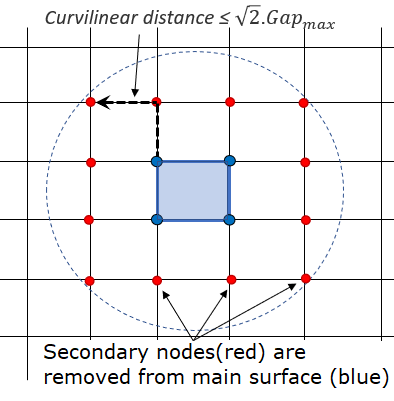
    Figure 2. Secondary nodes removed from node to surface contact


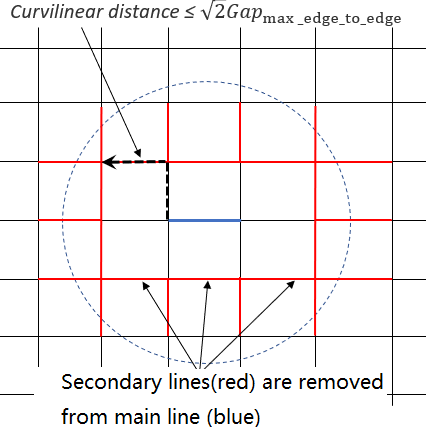
    Figure 3. Secondary lines removed from edge to edge contact

    In case of self-impact contact, when Curvilinear is smaller than 2 G a p (in initial configuration), then this secondary entity (node / line) will not be taken into account by this main entity (surface / line). The secondary entity will not be deleted from the contact for other other main entities. This also applies both nodes to surface and edge to edge contact as stated in the /INTER/TYPE7 and /INTER/TYPE11 comments.

  16. The sorting factor, Bumult is used to speed up the sorting algorithm.
  17. The sorting factor, Bumult is machine dependent.
  18. One node can belong to the two surfaces at the same time.
  19. If fric_ID is defined, the contact friction is defined in /FRICTION and the friction inputs (Ifric, C1, etc.) in this input card are not used.
    For friction formulation:
    • Whatever the friction flag Ifric, the Coulomb friction coefficient used in the TYPE11 interface is:
      (10)
      μ = F r i c
    • The friction flag Ifric only applies to the TYPE7 interface(s).
    • If the friction flag Ifric = 0 (default), the old static friction formulation is used:
      (11)
      F t μ F n

      While, μ = Fric with μ is Coulomb Friction coefficient.

    • For flag Ifric > 0, new friction models are introduced. In this case, the friction coefficient is set by a function μ = μ ( ρ , V ) MathType@MTEF@5@5@+= feaagKart1ev2aqatCvAUfeBSjuyZL2yd9gzLbvyNv2CaerbuLwBLn hiov2DGi1BTfMBaeXatLxBI9gBaerbd9wDYLwzYbItLDharqqtubsr 4rNCHbGeaGqiVu0Je9sqqrpepC0xbbL8F4rqqrFfpeea0xe9Lq=Jc9 vqaqpepm0xbbG8FasPYRqj0=yi0dXdbba9pGe9xq=JbbG8A8frFve9 Fve9Ff0dmeaabaqaciGacaGaaeqabaWaaeaaeaaakeaacqaH8oqBcq GH9aqpcaGI8oGaaiikaiabeg8aYjaacYcacaWGwbGaaiykaaaa@3F0A@ .
      Where,
      ρ
      Pressure of the normal force on the main segment
      V MathType@MTEF@5@5@+= feaagKart1ev2aqatCvAUfeBSjuyZL2yd9gzLbvyNv2CaerbuLwBLn hiov2DGi1BTfMBaeXatLxBI9gBaerbd9wDYLwzYbItLDharqqtubsr 4rNCHbGeaGqiVu0Je9sqqrpepC0xbbL8F4rqqrFfpeea0xe9Lq=Jc9 vqaqpepm0xbbG8FasPYRqj0=yi0dXdbba9pGe9xq=JbbG8A8frFve9 Fve9Ff0dmeaabaqaciGacaGaaeqabaWaaeaaeaaakeaacaWGwbaaaa@373A@
      Tangential velocity of the secondary node relative to the main segment
  20. Currently, the coefficients C1 through C6 are used to define a variable friction coefficient μ for new friction formulations.
    • Ifric = 1 (Generalized Viscous Friction law):(12)
      μ = Fric + C 1 p + C 2 V + C 3 p V + C 4 p 2 + C 5 V 2
    • Ifric = 2 (Modified Darmstad law): (13)
      μ = F r i c + C 1 e ( C 2 V ) p 2 + C 3 e ( C 4 V ) p + C 5 e ( C 6 V )
    • Ifric = 3 (Renard law):

      μ = C 1 + ( C 3 C 1 ) V C 5 ( 2 V C 5 ) if V [ 0 , C 5 ]

      μ = C 3 ( ( C 3 C 4 ) ( V C 5 C 6 C 5 ) 2 ( 3 2 V C 5 C 6 C 5 ) ) if V [ C 5 , C 6 ]

      μ = C 2 1 1 C 2 C 4 + ( V C 6 ) 2 if V C 6

      Where,
      C 1 = μ s C 4 = μ min
      C 2 = μ d C 5 = V cr 1
      C 3 = μ max C 6 = V c r 2
    • First critical velocity V c r 1 = C 5 must be different to 0 ( C 5 0 ).
    • First critical velocity V c r 1 = C 5 must be lower than the second critical velocity V c r 2 = C 6 ( C 5 < C 6 ).
    • The static friction coefficient C 1 and the dynamic friction coefficient C 2 , must be less than the maximum friction C 3 ( C 1 C 3 and C 2 C 3 ).
    • The minimum friction coefficient C 4 , must be less than the static friction coefficient C 1 and the dynamic friction coefficient C 2 ( C 4 C 1 and C 4 C 2 ).
    Table 1. Units for Friction Formulations
    Ifric Fric C1 C2 C3 C4 C5 C6
    1 [ 1 P a ] MathType@MTEF@5@5@+= feaagKart1ev2aqatCvAUfeBSjuyZL2yd9gzLbvyNv2CaerbuLwBLn hiov2DGi1BTfMBaeXatLxBI9gBaerbd9wDYLwzYbItLDharqqtubsr 4rNCHbGeaGqiVu0Je9sqqrpepC0xbbL8F4rqqrFfpeea0xe9Lq=Jc9 vqaqpepm0xbbG8FasPYRqj0=yi0dXdbba9pGe9xq=JbbG8A8frFve9 Fve9Ff0dmeaabaqaciGacaGaaeqabaWaaeaaeaaakeaadaWadaqaam aalaaabaGaaGymaaqaaiaaccfacaGGHbaaaaGaay5waiaaw2faaaaa @3AD5@ [ s m ] MathType@MTEF@5@5@+= feaagKart1ev2aaatCvAUfeBSjuyZL2yd9gzLbvyNv2CaerbuLwBLn hiov2DGi1BTfMBaeXatLxBI9gBaerbd9wDYLwzYbItLDharqqtubsr 4rNCHbGeaGqiVu0Je9sqqrpepC0xbbL8F4rqqrFfpeea0xe9Lq=Jc9 vqaqpepm0xbbG8FasPYRqj0=yi0dXdbba9pGe9xq=JbbG8A8frFve9 Fve9Ff0dmeaabaqaciGacaGaaeqabaWaaeaaeaaakeaadaWadaqaam aalaaabaGaae4Caaqaaiaab2gaaaaacaGLBbGaayzxaaaaaa@3A46@ [ s Pa m ] MathType@MTEF@5@5@+= feaagKart1ev2aaatCvAUfeBSjuyZL2yd9gzLbvyNv2CaerbuLwBLn hiov2DGi1BTfMBaeXatLxBI9gBaerbd9wDYLwzYbItLDharqqtubsr 4rNCHbGeaGqiVu0Je9sqqrpepC0xbbL8F4rqqrFfpeea0xe9Lq=Jc9 vqaqpepm0xbbG8FasPYRqj0=yi0dXdbba9pGe9xq=JbbG8A8frFve9 Fve9Ff0dmeaabaqaciGacaGaaeqabaWaaeaaeaaakeaadaWadaqaam aalaaabaGaae4CaaqaaiaabcfacaqGHbGaeyyXICTaaeyBaaaaaiaa wUfacaGLDbaaaaa@3E47@ [ 1 Pa 2 ] MathType@MTEF@5@5@+= feaagKart1ev2aqatCvAUfeBSjuyZL2yd9gzLbvyNv2CaerbuLwBLn hiov2DGi1BTfMBaeXatLxBI9gBaerbd9wDYLwzYbItLDharqqtubsr 4rNCHbGeaGqiVu0Je9sqqrpepC0xbbL8F4rqqrFfpeea0xe9Lq=Jc9 vqaqpepm0xbbG8FasPYRqj0=yi0dXdbba9pGe9xq=JbbG8A8frFve9 Fve9Ff0dmeaabaqaciGacaGaaeqabaWaaeaaeaaakeaadaWadaqaam aalaaabaGaaGymaaqaaiaabcfacaqGHbWaaWbaaSqabeaacaaIYaaa aaaaaOGaay5waiaaw2faaaaa@3BC6@ [ s 2 m 2 ] MathType@MTEF@5@5@+= feaagKart1ev2aaatCvAUfeBSjuyZL2yd9gzLbvyNv2CaerbuLwBLn hiov2DGi1BTfMBaeXatLxBI9gBaerbd9wDYLwzYbItLDharqqtubsr 4rNCHbGeaGqiVu0Je9sqqrpepC0xbbL8F4rqqrFfpeea0xe9Lq=Jc9 vqaqpepm0xbbG8FasPYRqj0=yi0dXdbba9pGe9xq=JbbG8A8frFve9 Fve9Ff0dmeaabaqaciGacaGaaeqabaWaaeaaeaaakeaadaWadaqaam aalaaabaGaae4CamaaCaaaleqabaGaaGOmaaaaaOqaaiaab2gadaah aaWcbeqaaiaaikdaaaaaaaGccaGLBbGaayzxaaaaaa@3C2C@
    2 [ 1 Pa 2 ] MathType@MTEF@5@5@+= feaagKart1ev2aqatCvAUfeBSjuyZL2yd9gzLbvyNv2CaerbuLwBLn hiov2DGi1BTfMBaeXatLxBI9gBaerbd9wDYLwzYbItLDharqqtubsr 4rNCHbGeaGqiVu0Je9sqqrpepC0xbbL8F4rqqrFfpeea0xe9Lq=Jc9 vqaqpepm0xbbG8FasPYRqj0=yi0dXdbba9pGe9xq=JbbG8A8frFve9 Fve9Ff0dmeaabaqaciGacaGaaeqabaWaaeaaeaaakeaadaWadaqaam aalaaabaGaaGymaaqaaiaabcfacaqGHbWaaWbaaSqabeaacaaIYaaa aaaaaOGaay5waiaaw2faaaaa@3BC6@ [ s m ] MathType@MTEF@5@5@+= feaagKart1ev2aaatCvAUfeBSjuyZL2yd9gzLbvyNv2CaerbuLwBLn hiov2DGi1BTfMBaeXatLxBI9gBaerbd9wDYLwzYbItLDharqqtubsr 4rNCHbGeaGqiVu0Je9sqqrpepC0xbbL8F4rqqrFfpeea0xe9Lq=Jc9 vqaqpepm0xbbG8FasPYRqj0=yi0dXdbba9pGe9xq=JbbG8A8frFve9 Fve9Ff0dmeaabaqaciGacaGaaeqabaWaaeaaeaaakeaadaWadaqaam aalaaabaGaae4Caaqaaiaab2gaaaaacaGLBbGaayzxaaaaaa@3A46@ [ 1 P a ] MathType@MTEF@5@5@+= feaagKart1ev2aqatCvAUfeBSjuyZL2yd9gzLbvyNv2CaerbuLwBLn hiov2DGi1BTfMBaeXatLxBI9gBaerbd9wDYLwzYbItLDharqqtubsr 4rNCHbGeaGqiVu0Je9sqqrpepC0xbbL8F4rqqrFfpeea0xe9Lq=Jc9 vqaqpepm0xbbG8FasPYRqj0=yi0dXdbba9pGe9xq=JbbG8A8frFve9 Fve9Ff0dmeaabaqaciGacaGaaeqabaWaaeaaeaaakeaadaWadaqaam aalaaabaGaaGymaaqaaiaaccfacaGGHbaaaaGaay5waiaaw2faaaaa @3AD5@ [ s m ] MathType@MTEF@5@5@+= feaagKart1ev2aaatCvAUfeBSjuyZL2yd9gzLbvyNv2CaerbuLwBLn hiov2DGi1BTfMBaeXatLxBI9gBaerbd9wDYLwzYbItLDharqqtubsr 4rNCHbGeaGqiVu0Je9sqqrpepC0xbbL8F4rqqrFfpeea0xe9Lq=Jc9 vqaqpepm0xbbG8FasPYRqj0=yi0dXdbba9pGe9xq=JbbG8A8frFve9 Fve9Ff0dmeaabaqaciGacaGaaeqabaWaaeaaeaaakeaadaWadaqaam aalaaabaGaae4Caaqaaiaab2gaaaaacaGLBbGaayzxaaaaaa@3A46@ [ s m ] MathType@MTEF@5@5@+= feaagKart1ev2aaatCvAUfeBSjuyZL2yd9gzLbvyNv2CaerbuLwBLn hiov2DGi1BTfMBaeXatLxBI9gBaerbd9wDYLwzYbItLDharqqtubsr 4rNCHbGeaGqiVu0Je9sqqrpepC0xbbL8F4rqqrFfpeea0xe9Lq=Jc9 vqaqpepm0xbbG8FasPYRqj0=yi0dXdbba9pGe9xq=JbbG8A8frFve9 Fve9Ff0dmeaabaqaciGacaGaaeqabaWaaeaaeaaakeaadaWadaqaam aalaaabaGaae4Caaqaaiaab2gaaaaacaGLBbGaayzxaaaaaa@3A46@
    3 [ m s ] MathType@MTEF@5@5@+= feaagKart1ev2aaatCvAUfeBSjuyZL2yd9gzLbvyNv2CaerbuLwBLn hiov2DGi1BTfMBaeXatLxBI9gBaerbd9wDYLwzYbItLDharqqtubsr 4rNCHbGeaGqiVu0Je9sqqrpepC0xbbL8F4rqqrFfpeea0xe9Lq=Jc9 vqaqpepm0xbba9pwe9Q8fs0=yqaqpepae9pg0FirpepeKkFr0xfr=x fr=xb9adbaqaaeGaciGaaiaabeqaamaabaabaaGcbaWaamWaaeaada Wcaaqaaiaab2gaaeaacaqGZbaaaaGaay5waiaaw2faaaaa@39DE@ [ m s ] MathType@MTEF@5@5@+= feaagKart1ev2aaatCvAUfeBSjuyZL2yd9gzLbvyNv2CaerbuLwBLn hiov2DGi1BTfMBaeXatLxBI9gBaerbd9wDYLwzYbItLDharqqtubsr 4rNCHbGeaGqiVu0Je9sqqrpepC0xbbL8F4rqqrFfpeea0xe9Lq=Jc9 vqaqpepm0xbba9pwe9Q8fs0=yqaqpepae9pg0FirpepeKkFr0xfr=x fr=xb9adbaqaaeGaciGaaiaabeqaamaabaabaaGcbaWaamWaaeaada Wcaaqaaiaab2gaaeaacaqGZbaaaaGaay5waiaaw2faaaaa@39DE@
  21. Friction filtering:
    If Ifiltr0, the tangential forces are smoothed using a filter:(14)
    F t = α F t + ( 1 α ) F t 1
    Where α coefficient is calculated from:
    • If Ifiltr= 1: α = X freq , simple numerical filter.
    • If Ifiltr = 2: α = 2 π X freq , standard -3dB filter, with X freq = d t T , and T MathType@MTEF@5@5@+= feaagKart1ev2aaatCvAUfeBSjuyZL2yd9gzLbvyNv2CaerbuLwBLn hiov2DGi1BTfMBaeXatLxBI9gBaerbd9wDYLwzYbItLDharqqtubsr 4rNCHbGeaGqiVu0Je9sqqrpepC0xbbL8F4rqqrFfpeea0xe9Lq=Jc9 vqaqpepm0xbbG8FasPYRqj0=yi0dXdbba9pGe9xq=JbbG8A8frFve9 Fve9Ff0dmeaabaqaciGacaGaaeqabaWaaeaaeaaakeaacaWGubaaaa@3737@ is filtering period.
    • If Ifiltr = 3: α = 2 π X f r e q d t , standard -3dB filter, with X f r e q is cutting frequency.

      The filtering coefficient X f r e q should have a value between 0 and 1.

  22. Friction penalty formulation Iform
    • If Iform = 1, (default) viscous formulation, the friction forces are:(15)
      F t = min ( μ F n , F a d h )

      While an adhesion force is computed as:

      F a d h = C V t with C = V I S F 2 K m

    • If Iform = 2, stiffness formulation, the friction forces are:(16)
      F t n e w = min ( μ F n , F a d h )

      While an adhesion force is computed as:

      F a d h = F t o l d + Δ F t with Δ F t = K V t d t

      Where, V t is the tangential velocity of the secondary node relative to the main segment.

  23. If the time step of a secondary node in this contact becomes less than dtmin, the secondary node is deleted from the contact and a warning message is printed in the output file. This dtmin value takes precedence over any model interface minimum time step entered in /DT/INTER/DEL.
  24. Edges to edge contact flag Iedge:
    • Iedge = 1: only external edges are generated from contact surfaces which defined by SHELL parts, it is recommended for optimized performance. Cannot be used when the surface contains only solid parts which lead to an empty line and then error message will be printed.
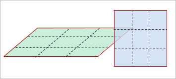

      Figure 4.
    • Iedge = 2: all edges are generated from contact surfaces.
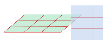

      Figure 5.
  25. Heat exchange:
    By Ithe =1 (heat transfer activated) to consider heat exchange and heat friction in contact.
    • If Ithe_form = 0, then heat exchange is between shell and constant temperature contact Tint.
    • If Ithe_form = 1, then heat exchange is between all contact pieces.

      Tint is used only when Ithe_form= 0. In this case, the temperature of main side assumed to be constant (equal to Tint). If Ithe_form=1, then Tint is not taken into account, for the nodal temperature of main side will be considered.

    Heat exchange coefficient:
    • If fct_IDK = 0, then Kthe is heat exchange coefficient and heat exchange depends only on heat exchange surface.
    • If fct_IDK0, then Kthe is a scale factor and the heat exchange will depend on the contact pressure:(17)
      K = K the f K ( Ascale K , P )
    • While f K is the function of fct_IDK.
  26. Heat Friction:
    • Frictional energy is converted into heat when Ithe > 0 for interface.
    • Fheats and Fheatm are defined as the fraction of frictional energy and distributed respectively to the secondary side and main side. So generally:(18)
      Fheat s + Fheat m 1.0

      When both Fheats and Fheatm are equal to 0, the conversion of the frictional sliding energy to heat is not activated.

    • The frictional heat QFric is defined:
      • If Iform= 2 (a stiffness formulation):
        Secondary side: (19)
        Q Fric = Fheat s ( F adh F t ) K F t
        Main side: (20)
        Q Fric = Fheat m ( F adh F t ) K F t
        (Ithe_form= 1)
      • If Iform= 1 (a penalty formulation):
        Secondary side: (21)
        Q Fric = Fheat s C V t 2 d t
        Main side: (22)
        Q Fric = Fheat m C V t 2 d t
        (Ithe_form= 1)
  27. Radiation:
    Radiation is considered in contact if F r a d 0 and the distance, d MathType@MTEF@5@5@+= feaagKart1ev2aqatCvAUfeBSjuyZL2yd9gzLbvyNv2CaerbuLwBLn hiov2DGi1BTfMBaeXatLxBI9gBaerbd9wDYLwzYbItLDharqqtubsr 4rNCHbGeaGqiVu0Je9sqqrpepC0xbbL8F4rqqrFfpeea0xe9Lq=Jc9 vqaqpepm0xbbG8FasPYRqj0=yi0dXdbba9pGe9xq=JbbG8A8frFve9 Fve9Ff0dmeaabaqaciGacaGaaeqabaWaaeaaeaaakeaacaWGebWaaS baaSqaaiaadkhacaWGHbGaamizaaqabaaaaa@3A1A@ , of the secondary node to the main segment is:(23)
    Gap < d < D rad
    While D r a d MathType@MTEF@5@5@+= feaagKart1ev2aqatCvAUfeBSjuyZL2yd9gzLbvyNv2CaerbuLwBLn hiov2DGi1BTfMBaeXatLxBI9gBaerbd9wDYLwzYbItLDharqqtubsr 4rNCHbGeaGqiVu0Je9sqqrpepC0xbbL8F4rqqrFfpeea0xe9Lq=Jc9 vqaqpepm0xbbG8FasPYRqj0=yi0dXdbba9pGe9xq=JbbG8A8frFve9 Fve9Ff0dmeaabaqaciGacaGaaeqabaWaaeaaeaaakeaacaWGebWaaS baaSqaaiaadkhacaWGHbGaamizaaqabaaaaa@3A1A@ is the maximum distance for radiation computation. The default value for D r a d MathType@MTEF@5@5@+= feaagKart1ev2aqatCvAUfeBSjuyZL2yd9gzLbvyNv2CaerbuLwBLn hiov2DGi1BTfMBaeXatLxBI9gBaerbd9wDYLwzYbItLDharqqtubsr 4rNCHbGeaGqiVu0Je9sqqrpepC0xbbL8F4rqqrFfpeea0xe9Lq=Jc9 vqaqpepm0xbbG8FasPYRqj0=yi0dXdbba9pGe9xq=JbbG8A8frFve9 Fve9Ff0dmeaabaqaciGacaGaaeqabaWaaeaaeaaakeaacaWGebWaaS baaSqaaiaadkhacaWGHbGaamizaaqabaaaaa@3A1A@ is computed as the maximum of:
    • Upper value of the Gap (at time 0) among all nodes
    • Smallest side length of secondary element

    It is recommended not to set the value too high for D r a d MathType@MTEF@5@5@+= feaagKart1ev2aqatCvAUfeBSjuyZL2yd9gzLbvyNv2CaerbuLwBLn hiov2DGi1BTfMBaeXatLxBI9gBaerbd9wDYLwzYbItLDharqqtubsr 4rNCHbGeaGqiVu0Je9sqqrpepC0xbbL8F4rqqrFfpeea0xe9Lq=Jc9 vqaqpepm0xbbG8FasPYRqj0=yi0dXdbba9pGe9xq=JbbG8A8frFve9 Fve9Ff0dmeaabaqaciGacaGaaeqabaWaaeaaeaaakeaacaWGebWaaS baaSqaaiaadkhacaWGHbGaamizaaqabaaaaa@3A1A@ , which may reduce the performance of Radioss Engine.

    A radiant heat transfer conductance is computed as:(24)
    h rad = F rad ( T m 2 + T s 2 ) ( T m + T s )
    with(25)
    F rad = σ 1 ε 1 + 1 ε 2 1
    Where,
    σ = 5.669 × 10 8 [ W m 2 K 4 ]
    Stefan Boltzman constant
    ε 1
    Emissivity of secondary surface
    ε 2
    Emissivity of main surface