TYPE7
Contact surfaces and solid element.
For contacts that involve solid elements, it is not necessary to create extra “skin” shell elements on the face of the solid elements. To define the contact surface on the entire face of a part, use /SURF/PART/EXT. For contact in a local area, /SURF/SEG to define specific contact segments.
How to chose the main and secondary.
If the contact is neither self-impacting nor symmetric, then it is recommended to choose the coarse mesh on the main side for better contact detection. If the contact is self-impacting or symmetric, then it does not matter because all the elements and nodes will be both main and secondary.
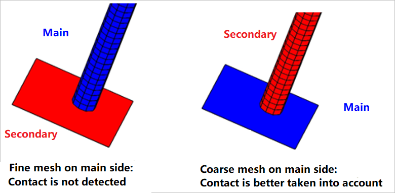
Figure 1.
In case both meshes are of the same size, the stiffer structure on the main side should generally be chosen.
Initial contact stiffness
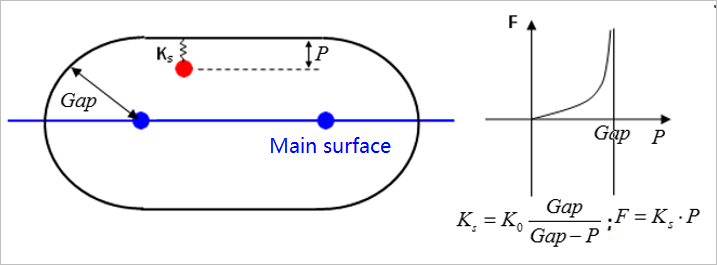
Figure 2.
The initial stiffness K0 (that is to say the stiffness when the node enters the gap), computed by Radioss takes into account either both main and secondary stiffness (Istf =2 to 5) or only main stiffness (old way corresponding to Istf =0).
The stiffness is computed according to geometrical and material characteristics of the elements on main side and/or on secondary side (depending on the value of Istf).
- Young's modulus of the material
- Thickness of the shell
- Bulk modulus of the material
- Area of the segment
- Volume of the solid element
- Stfac
- Scale factor which can be modified by the user with a default value equal to 1
The interface stiffness during the simularion is a nonlinear function of the penetration p and goes to an infinite value when the secondary node gets very close to the main segment in order to prevent the node from crossing the main segment and hence, better represent contact.
Time step reductions caused by contact.
The time step, based on contact is calculated as described in Contact Interface Time Step of the User Guide. Based on the time step formulas, if the contact stiffness is too large, then the time step will drop based on the interface nodal time step. For nonlinear contacts (TYPE7, TYPE11, and TYPE19), the time step can drop if a node penetrates the contact gap too quickly.
If there is a reduction in the time step of a simulation, due to a TYPE7 contact interface, first check to make sure there are not any initial penetration or intersections in the model at the beginning. This can be done using a pre-processor and by checking the Radioss Starter output file for warning messages.
Next, check the contact gap in the interface. The value must be physically realistic and based on shell thicknesses (Igap =1, 2, or 3) in case of contact between shells. For shells, enter a Gapmin that is half of the thinnest part.
For contact between solid elements, enter a small Gapmin to avoid initial penetrations. If however the Gapmin value is too small, the contact force is applied very quickly which can cause issues. In this case switch to a contact that allows zero contact gap between solid elements such as /INTER/TYPE25 or /INTER/TYPE24.
If no Gapmin is specified, Radioss calculates a default value for Gapmin that is written to the Starter output file.
Also, check stiffness' on secondary and main side. If they vary by a ratio greater than 100, use Istf =2 or 3, so that the interface initial stiffness will be greater and even though the interface initial time step will be lower, this will increase the time step, if penetration is large. Indeed, the penetration will be lower for the same energy absorption and thus for “stopping the secondary node”.
| Shells | Solids | |
|---|---|---|
| Stiffness on Secondary side | ||
| Stiffness on Main side |
- Segment area
- Volume of the solid
- Bulk modulus
- Young modulus of the material
- Thickness of the shell
If some elements fail on the main side or on the secondary side of the interface, it is important to set Idel =2 (or Idel =1) for this interface. This will prevent nodes connected to deleted elements whose stresses are released to impact with a possible high velocity.