Time Step
Why is the cycle time step very small?
- In case of an element, check the related material (especially its Young modulus and
density in case of an elastic-plastic material; and its viscosity in case of a
visco-elastic material). There must not be an error in the units system that this data
is given in.
Check the size of the element, since
Where,- Characteristic length of the element
- Material sound speed
- Scale factor
- In case of a node, check the characteristics of connected elements. If the node is on
the main side or the secondary side of an interface, this interface must be
verified.If a main node of a rigid body gives the time step, check the rigid body inertia reported in the output file (Runname_0000.out), at:
- Rigid Body Initialization (for a rigid body made of only a few nodes, it may be necessary to set a spherical inertia).
- In case of an interface, the gap of the interface must be verified if some failure happens on the main or the secondary side of the interface.
Using beam elements (/PROP/BEAM) the time step given by the Starter in output file (Runname_0000.out) and the time step given by the Engine on this element are different; is this normal?
For this time step computation, Radioss Starter does not take into account the damping coefficients; while Radioss Engine does.
Particularly in the case of thick beams, due to flexural damping, the time step computed by Engine may be quite different from the one computed by Starter.
The beam formulation in property type /PROP/TYPE3 (BEAM) is not well-suited for thick beams.
How is the time step computed on main nodes of rigid bodies?
In case of a rigid body and nodal time step, the time step for stability is computed at the main node (the nodal time step at secondary nodes does not need to be considered).
- Mass of the rigid body
- Lower principal inertia of the rigid body inertia matrix around the main node
- Stiffness reported to the main node
- Rotation stiffness reported to the main node
The time step at the main node of the rigid body is computed by reporting stiffness at secondary nodes to the main node.
The mass and inertia of the rigid body depends on the flag ICoG in /RBODY.
For instance, if ICoG =4, the mass that is input in the rigid body option is considered; whereas for ICoG =2, the mass that is input in the rigid body option is added to the secondary nodes mass.
Using /DT/INTER/DEL in Radioss Engine file (Runname_0001.rad). How is it possible that the time step is given in the output file (Runname_0001.out) by an interface, and is lower than the minimum value given in /DT/INTER/DEL?
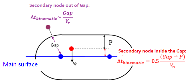
Figure 1.
- A kinematic time step is computed for the whole interface:
(2) Where, is an estimation of the maximum relative speed between main nodes and secondary nodes.
This time step computation prevents a secondary node from crossing the main surface while ensuring the performances of searching the contacts through the interface.
- For the nodes which lie within the gap of a main segment, the kinematic time step is
computed more precisely for this secondary/main couple:
(3) If this time step is lower than the value given in option /DT/INTER/DEL, then the secondary node is suppressed from the interface and the following message is written to the output file of Radioss Engine:**WARNING MINIMUM TIME STEP 0.3001E-03 IN INTERFACE 1 REMOVE SECONDARY NODE 526210 FROM INTERFACE
- For the nodes which lie within the gap of a main segment, the stability time step is computed for this secondary/main couple. If it is lower than the minimum time step given in option /DT/INTER/DEL, the secondary node is also suppressed from the interface.
In certain situations, the kinematic time step of the interface may be lower than the minimum time step which was specified in option /DT/INTER/DEL. If such a situation is encountered from the beginning of the computation, the value of the Gap may be checked.
How is it possible that the time step is controlled by a node even while using elementary time step (i.e did not specify /DT/NODA)?
CYCLE	     TIME	 TIME-STEP	ELEMENT	ERROR	I-ENERGY	K-ENERGY T	K-ENERGY R	EXT-WORK	MAS.ERR
100	0.1846E0-02	0.1846E-04    NODA   123        0.0%    0.4261E-04      0.6069E-02	0.3660E-25     0.6112E-02        0.000
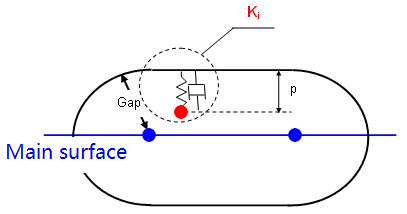
Figure 2.
In case of an impact between a secondary node and a main segment, the stiffness of the penalty spring for this impact is applied to both secondary and main nodes, in order to ensure stability.
More precisely, Interface TYPE7 associates a penalty spring and damping, so that an equivalent stiffness to the whole system is considered.
- Nodal mass
- Nodal stiffness
In case the deck includes Interface TYPE7, TYPE10, TYPE11 or TYPE19, this time step is always computed at all nodes of the deck, in order to ensure stability even if an elementary time step is used.
But when the time step is taken onto a node, this node is probably impacting (otherwise nodal time step computed with is greater than elementary time step).
What is the difference between the messages "Delete Secondary Node" and "Remove Secondary Node" concerning interfaces TYPE7 in the output file (Runname_0001.out)?
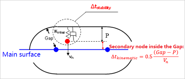
Figure 3.
If it is such that , then the secondary node is suppressed from the interface.
The message "Delete Secondary Node" is written when the stability time step of the interface for the secondary/main couple; which is considered is lower than the minimum time step which was specified in option /DT/INTER/DEL.
- Minimum nodal mass among the secondary node and the nodes of the main segment.
- Interface stiffness for the secondary/main couple which is considered ( is an equivalent stiffness to the penalty spring and the damping which are applied between the secondary node and the main segment).
When the stability time step for the secondary/main couple is such that , then the secondary node is suppressed from the interface.
It is possible that those messages would be written several times within the same cycle for the same node and the same interface (if the node impacts several main segments within the same cycle and several contacts get a lower time step than the minimum time step which was specified in option /DT/INTER/DEL).