Property and Elements
ERROR ID: 28 for /PROP/TYPE16
In Radioss versions before 2017, this error means the number of layers defined for /PROP/TYPE16 was set to N>1. To fix this issue, set N=1.
Strain formulations for /PROP/CONNECT
Layer thickness and position calculation
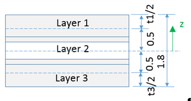
In the properties /PROP/TYPE11 and /PROP/TYPE16, the properties, options Thick, ti and Ipos will affect the layer thickness and layer position.
Ipos = 0:
The layer positions Zi are automatically calculated with regard to layer thicknesses.
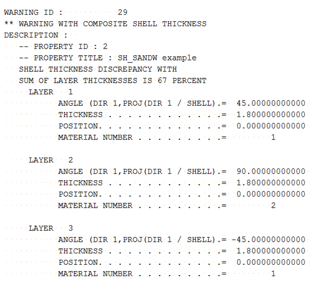
If the sum of layer thickness is different from the input value Thick, a warning message is displayed. Radioss then adjusts the layer thickness and layer position.
Shell thickness Thick (1.8) is not equal to the sum of layer thickness (0.5+0.6+0.5=1.6) in the input.
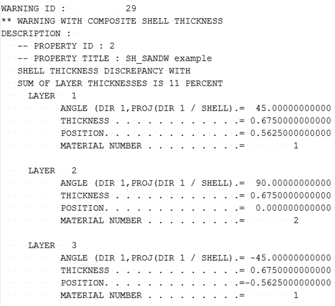
During the computation, Radioss uses the sum of input layer thickness (1.6) to adjust each layer thickness using and the layer thickness are automatically updated.
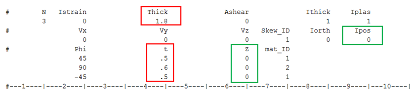
Figure 1.

| Adjusted Layer Thickness | Layer Position |
|---|---|
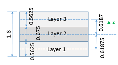
Figure 2.
Figure 3.
Ipos= 1:
- If multiple layers have the same position and thus are overlapping, a warning message is displayed. In this case, the layer thickness will also be adjusted.
If Ipos=1 and the layer position Zi is not defined or =0.0, then the layers are all in the same position and overlap each other.
During the computation, Radioss takes the thickness of the thickest layer (0.6) to adjust each layer thickness with .
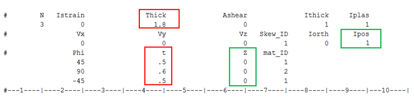
Figure 4.
| Adjusted Layer Thickness | Layer Position |
|---|---|
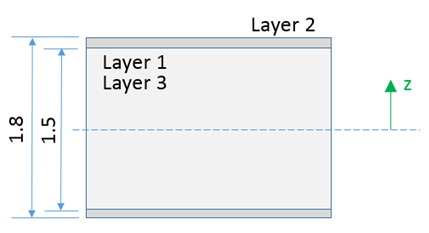
Figure 5.
- If multiple layers may have a small overlap or a gap, a warning message is displayed. In this case, the layer thickness and layer position will be also adjusted.
If Ipos=1 and you have defined Zi with a small overlap, layers thickness and layer position will be adjusted.
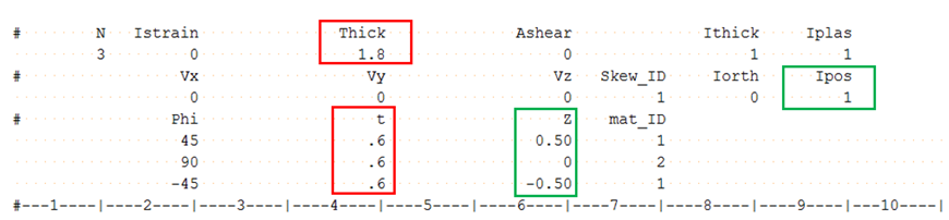
Figure 6.
| Adjusted Layer Thickness | Layer Position |
|---|---|
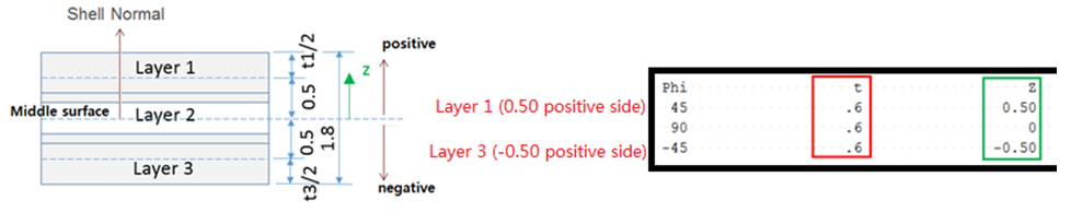
Figure 7.
Zero or Negative Volume messages
** ERROR:  ZERO OR NEGATIVE 3D SOLID VOLUME
ZERO OR NEGATIVE VOLUME 3D-ELEMENT NB 1
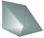
Figure 8.
When using fully-integrated solid elements, the element is decomposed into sub-volumes associated to with each integration point. If the element is badly warped, one sub-volume could be negative even though the total volume of the element is positive. To fix this issue, remesh the part or switch to an element with 1 integration point.
WARNING ZERO OR NEGATIVE VOLUME: 3D-ELEMENT ID: 1330, TOTAL (SMALL) STRAIN OPTION
IS USED BY ELEMENT
Which indicates that the element has a zero or negative volume which would normally cause the analysis to top. By automatically switching to a small strain formulation, the analysis can continue without stopping. If the element originally used full geometric nonlinear strain (Ismstr = 2, 4), then the switch to small strain uses the element shape from cycle before the negative volume. If the element originally used Lagrange type total strain (Ismstr = 10, 12), then switch to total strain uses the element shape at time=0.0. This automatic switching can be disabled by using the Engine option /NEGVOL/STOP.
Zero or Negative Volume
This happens when solid elements are very deformed and their characteristic length goes to 0 and; thus, the element has zero or negative volume. You may notice that before getting this error message, the time step of the element is reducing.
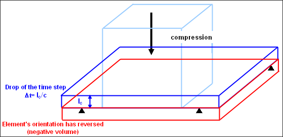
Figure 9.
To solve this problem, first check that the material properties are correct in the model. Often this issue is caused by a mistake in the material property input which causes the material to be too soft.
To prevent the drop in time step and negative volume issue, use Ismstr =2 or 12 in the solid property or in the option /DEF_SOLID. Then in the Radioss Engine file (Runname_0001.rad) use the option /DT/BRICK/CST which will set the time step value at which the solid elements will switch to small strain. The time step specified is recommended to be two to four times smaller than the constant time step is specified in /DT/NODA/CST.
This means that the solid elements using Ismstr =2 will use large strain formulation while their time step remains greater than , and will then switch to small strain formulation. Solid elements using Ismstr =12 will use the Lagrange type total strain formulation while their time step remains greater than , and will then switch to total small strain formulation.
Their volume will then remain constant and the element can even reverse its orientation. The drop in their time step normally stops except for some materials, especially viscous materials.
Integration points through the shell thickness
If only one integration point is used, a membrane only behavior will be obtained (except with LAW1, up to V44) which can be used to model fabric that has no bending stiffness.
When a material is elastic, three integration points give an exact solution and the bending moments are exactly integrated through the thickness of the shell.
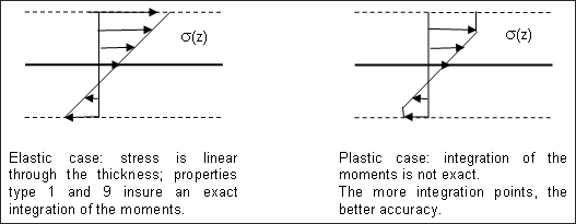
Figure 10.
Different results for shell properties
For shell elements that use the same material and through thickness integration points, the results can be different depending on which shell property is used. The through thickness integration used by /PROP/SHELL and /PROP/SH_ORTH defines the integration points and weights to integrate exactly the bending moments in the elastic case when three integration points are used.
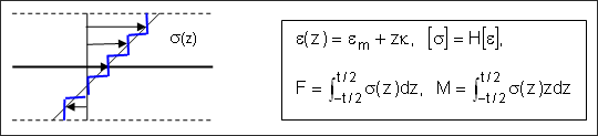
Figure 11.
- Elastic case:
- Stress is linear through the thickness; an integration of forces step-by-step is exact, but the integration of moments, step-by-step is not exact since ; where, z is quadratic.
QEPH versus Belytschko shell
QEPH shells (Ishell=24) are more accurate for elastic or elasto-plastic loads, whatever the loading type - quasi-static or dynamic. The Belytschko shells (Ishell=1-4), will often hourglass.
QEPH shells (Ishell=24) will give better results if the mesh is fine enough. When using a coarse mesh, this formulation will be too stiff and some local buckling phenomena could be missed. In the case of a coarse mesh, the Belytschko (Ishell=4) shells often give better results.
NULL DIAMETER SPH ERROR 174?
MESSAGE ID :          174
** ERROR : NULL DIAMETER FOR SPH PARTICLE ID=52032255
This message means that an SPH particle is compressed so much that its diameter is zero which causes this error.
Most of the time, this is due to an input error, such as entering information in the wrong units. It is recommended to check the consistency between mass, density, diameter and particle pitch. Also, review that the material input is correct.
To see the particle diameter, review the “Diameter” animation contour is always available for the particles.