/MAT/LAW83

Block Format Keyword This law describes the Connection material, which can be used to model spotweld, welding line, glue, or adhesive layers in laminate composite material.

Elastic and elastoplastic behavior can be defined. The plastic behavior of the material can be coupled in normal and shear directions for corresponding displacement-rates. This material is applicable only to solid hexahedron elements (/BRICK) and the material time-step does not depend on element height.

Format

(1) (2) (3) (4) (5) (6) (7) (8) (9) (10)
/MAT/LAW83/mat_ID/unit_ID
mat_title
ρ i                
E G Imass          
fct_ID1   Y_scale1 X_scale1 α β
RN RS Fsmooth Fcut      
fct_IDN fct_IDS XSCALE            

Definitions

Field Contents SI Unit Example
mat_ID Material identifier

(Integer, maximum 10 digits)

 
unit_ID Unit Identifier

(Integer, maximum 10 digits)

 
mat_title Material title

(Character, maximum 100 characters)

 
ρ i Initial density

(Real)

[ kg m 3 ]
E Young's (stiffness) modulus per unit length.

(Real)

[ Pa m ] MathType@MTEF@5@5@+= feaagKart1ev2aaatCvAUfeBSjuyZL2yd9gzLbvyNv2CaerbuLwBLn hiov2DGi1BTfMBaeXatLxBI9gBaerbd9wDYLwzYbItLDharqqtubsr 4rNCHbGeaGqiVu0Je9sqqrpepC0xbbL8F4rqqrFfpeea0xe9Lq=Jc9 vqaqpepm0xbba9pwe9Q8fs0=yqaqpepae9pg0FirpepeKkFr0xfr=x fr=xb9adbaqaaeaaciGaaiaabeqaamaabaabaaGcbaWaamWaaeaada WcaaqaaiaadcfacaWGHbaabaGaamyBaaaaaiaawUfacaGLDbaaaaa@3AA3@
G Shear (stiffness) modulus per unit length.

Default = E (Real)

[ P a m ] MathType@MTEF@5@5@+= feaagKart1ev2aaatCvAUfeBSjuyZL2yd9gzLbvyNv2CaerbuLwBLn hiov2DGi1BTfMBaeXatLxBI9gBaerbd9wDYLwzYbItLDharqqtubsr 4rNCHbGeaGqiVu0Je9sqqrpepC0xbbL8F4rqqrFfpeea0xe9Lq=Jc9 vqaqpepm0xbba9pwe9Q8fs0=yqaqpepae9pg0FirpepeKkFr0xfr=x fr=xb9adbaqaaeaaciGaaiaabeqaamaabaabaaGcbaWaamWaaeaada WcaaqaaiaadcfacaWGHbaabaGaamyBaaaaaiaawUfacaGLDbaaaaa@3AA3@
Imass Mass calculation flag.
= 0 (Default)
Element mass is calculated using density and volume.
= 1
Element mass is calculated using density and (means of upper and lower) area.

(Integer)

 
fct_ID1 Normalized yield curve that specifies true stress vs. plastic displacement.

(Integer)

 
Y_scale1 Scale factor for ordinate of the normalized function, fct_ID1. 10

Default = 1.0 (Real)

 
X_scale1 Scale factor for abscissa of the function, fct_ID1. 10

Default = 1.0 (Real)

[ m ]
α Angle parameter used in the calculation of the effective true stress. 8

Default = 0.0 (Real)

[ rad ]
β Exponent used in the calculation of the effective true stress. 8

Default = 2.0 (Real)

 
RN Maximum true stress in normal direction used in the calculation of effective true stress.

Default = 1.0 (Real)

[ Pa ]
RS Maximum true stress in shear direction used in the calculation of effective true stress.

Default = 1.0 (Real)

[ Pa ]
Fsmooth Displacement rate filtering flag.
= 0 (Default)
No displacement rate filtering.
= 1
Displacement rate filtering.

(Integer)

 
Fcut Cutoff frequency for the displacement rate filtering.

Default = 1030 (Real)

[Hz]
fct_IDN Function identifier defining a scale factor vs. the plastic displacement rate in normal direction. 9

Default = 0 (Integer)

 
fct_IDS Function identifier defining a scale factor vs. the plastic displacement rate in shear direction. 9

Default = 0 (Integer)

 
XSCALE Scale factor for the abscissa of functions fct_IDN and fct_IDS. 9

Default = 1.0 (Real)

[ m s ] MathType@MTEF@5@5@+= feaagKart1ev2aaatCvAUfeBSjuyZL2yd9gzLbvyNv2CaerbuLwBLn hiov2DGi1BTfMBaeXatLxBI9gBaerbd9wDYLwzYbItLDharqqtubsr 4rNCHbGeaGqiVu0Je9sqqrpepC0xbbL8F4rqqrFfpeea0xe9Lq=Jc9 vqaqpepm0xbba9pwe9Q8fs0=yqaqpepae9pg0FirpepeKkFr0xfr=x fr=xb9adbaqaaeGaciGaaiaabeqaamaabaabaaGcbaWaamWaaeaada Wcaaqaaiaab2gaaeaacaqGZbaaaaGaay5waiaaw2faaaaa@39DE@

Example (Connect)

In this example, normal yield curve is fct_ID1=200. Maximal normal true stress is 0.2 Gpa and maximal shear true stress is 0.4 Gpa. β = 2 which is used to fit the mixed-mode load case (30° or 60°) of connection. α = 0 , peel effect is not considered.
#RADIOSS STARTER
#---1----|----2----|----3----|----4----|----5----|----6----|----7----|----8----|----9----|---10----|
/UNIT/1 
unit for mat
                  kg                  mm                  ms
#---1----|----2----|----3----|----4----|----5----|----6----|----7----|----8----|----9----|---10----|
#-  2. MATERIALS:
#---1----|----2----|----3----|----4----|----5----|----6----|----7----|----8----|----9----|---10----|
/MAT/LAW83/1/1
CONNECT MATERIAL
#              RHO_I
              7.8E-6
#                  E                   G     Imass 
                  20                             0
#  Fct_ID1                      Y_scale1            X_scale1               ALPHA                BETA
       200                             1                   1                   0                   2
#                 RN                  RS   Fsmooth                Fcut
                  .2                  .4         0                   0
#  Fct_IDN   Fct_IDS              XSCALE
         0         0                   0
/FAIL/SNCONNECT/1/1
#            ALPHA_0              BETA_0             ALPHA_F              BETA_F  Ifail_so      ISYM
                   0                   2                   0                   2         1         1
#   Fct_0N    Fct_0S    Fct_FN    Fct_FS            XSCALE_0            XSCALE_F           AREAscale
      2001      2002      2003      2004                   1                   1                   0
#---1----|----2----|----3----|----4----|----5----|----6----|----7----|----8----|----9----|---10----|
#-  3. FUNCTIONS:
#---1----|----2----|----3----|----4----|----5----|----6----|----7----|----8----|----9----|---10----|
/FUNCT/200
MAT83 curve
#                  X                   Y
                   0                   1                                                            
                   1                   1                                                            
#---1----|----2----|----3----|----4----|----5----|----6----|----7----|----8----|----9----|---10----|
/FUNCT/2001
Fct_0N
#                  X                   Y
                   0                  .5                                                            
                   1                  .5                                                            
#---1----|----2----|----3----|----4----|----5----|----6----|----7----|----8----|----9----|---10----|
/FUNCT/2002
Fct_0S
#                  X                   Y
                   0                  .5                                                            
                   1                  .5                                                            
#---1----|----2----|----3----|----4----|----5----|----6----|----7----|----8----|----9----|---10----|
/FUNCT/2003
Fct_fN
#                  X                   Y
                   0                   1                                                            
                   1                   1                                                            
#---1----|----2----|----3----|----4----|----5----|----6----|----7----|----8----|----9----|---10----|
/FUNCT/2004
Fct_fS
#                  X                   Y
                   0                   1                                                            
                   1                   1                                                            
#---1----|----2----|----3----|----4----|----5----|----6----|----7----|----8----|----9----|---10----|
#ENDDATA
/END
#---1----|----2----|----3----|----4----|----5----|----6----|----7----|----8----|----9----|---10----|

Comments

  1. This law is compatible with 8-noded hexadedron elements (/BRICK) only. It is only compatible with /PROP/TYPE43.
  2. Stiffness modulus and yield curve:
    • The stiffness modulus and stresses are defined per displacement in order to be independent from the initial height of the solid element.

      For example, E MathType@MTEF@5@5@+= feaagKart1ev2aaatCvAUfeBSjuyZL2yd9gzLbvyNv2CaerbwvMCKf MBHbqefqvATv2CG4uz3bIuV1wyUbqedmvETj2BSbqefm0B1jxALjhi ov2DaebbnrfifHhDYfgasaacH8srps0lbbf9q8WrFfeuY=Hhbbf9v8 qqaqFr0xc9pk0xbba9q8WqFfea0=yr0RYxir=Jbba9q8aq0=yq=He9 q8qqQ8frFve9Fve9Ff0dmeaacaGacmGadaWaaiqacaabaiaafaaake aacaWGfbaaaa@39A1@ =210000 MPa/mm means that the normal stress increases by 210000 MPa for each 1 mm of elongation until the yield stress limit specified by the yield stress curve is reached.

    • The stiffness in shear direction is assumed to be equal to the stiffness modulus, E MathType@MTEF@5@5@+= feaagKart1ev2aaatCvAUfeBSjuyZL2yd9gzLbvyNv2CaerbwvMCKf MBHbqefqvATv2CG4uz3bIuV1wyUbqedmvETj2BSbqefm0B1jxALjhi ov2DaebbnrfifHhDYfgasaacH8srps0lbbf9q8WrFfeuY=Hhbbf9v8 qqaqFr0xc9pk0xbba9q8WqFfea0=yr0RYxir=Jbba9q8aq0=yq=He9 q8qqQ8frFve9Fve9Ff0dmeaacaGacmGadaWaaiqacaabaiaafaaake aacaWGfbaaaa@39A1@ (Figure 1).
    • The Poisson's ratio is equal to zero.
    • After reaching the yield stress (defined in fct_ID11), the material goes into the plastic phase. After reach the maximum stress RN (in tension) or RS (in shear), the stress in material will not increase (Figure 1).
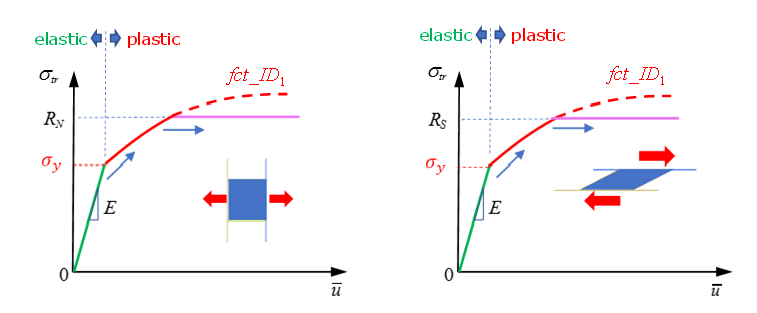

      Figure 1.
    • The plastic displacement is accounted for when fct_ID1 is specified. This is usually a non-decreasing function, which represents true stress as a function of the plastic displacement. The first abscissa value of the function should be “0” and the first ordinate value is the "yield stress". The function may have a stress decrease portion to model material damage.
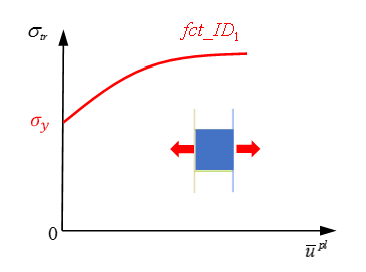

      Figure 2.
  3. Plastic displacement.
    The complete element displacement u ¯ MathType@MTEF@5@5@+= feaagKart1ev2aaatCvAUfeBSjuyZL2yd9gzLbvyNv2CaerbuLwBLn hiov2DGi1BTfMBaeXatLxBI9gBaerbd9wDYLwzYbItLDharqqtubsr 4rNCHbGeaGqiVu0Je9sqqrpepC0xbbL8F4rqqrFfpeea0xe9Lq=Jc9 vqaqpepm0xbba9pwe9Q8fs0=yqaqpepae9pg0FirpepeKkFr0xfr=x fr=xb9adbaqaaeGaciGaaiaabeqaamaabaabaaGcbaGabmyDayaara aaaa@3708@ can be subdivided into an elastic portion u ¯ e MathType@MTEF@5@5@+= feaagKart1ev2aaatCvAUfeBSjuyZL2yd9gzLbvyNv2CaerbuLwBLn hiov2DGi1BTfMBaeXatLxBI9gBaerbd9wDYLwzYbItLDharqqtubsr 4rNCHbGeaGqiVu0Je9sqqrpepC0xbbL8F4rqqrFfpeea0xe9Lq=Jc9 vqaqpepm0xbba9pwe9Q8fs0=yqaqpepae9pg0FirpepeKkFr0xfr=x fr=xb9adbaqaaeGaciGaaiaabeqaamaabaabaaGcbaGabmyDayaara WaaWbaaSqabeaacaWGLbaaaaaa@381F@ (before yield stress is reached) and a portion of the plastic displacement u ¯ p l MathType@MTEF@5@5@+= feaagKart1ev2aaatCvAUfeBSjuyZL2yd9gzLbvyNv2CaerbuLwBLn hiov2DGi1BTfMBaeXatLxBI9gBaerbd9wDYLwzYbItLDharqqtubsr 4rNCHbGeaGqiVu0Je9sqqrpepC0xbbL8F4rqqrFfpeea0xe9Lq=Jc9 vqaqpepm0xbba9pwe9Q8fs0=yqaqpepae9pg0FirpepeKkFr0xfr=x fr=xb9adbaqaaeGaciGaaiaabeqaamaabaabaaGcbaGabmyDayaara WaaWbaaSqabeaacaWGWbGaamiBaaaaaaa@391B@ . In the simplest case of uni-axial tension and compression, plastic displacement is calculated as:(1)
    u ¯ p l = u ¯ u ¯ e = u ¯ σ t r E MathType@MTEF@5@5@+= feaagKart1ev2aaatCvAUfeBSjuyZL2yd9gzLbvyNv2CaerbuLwBLn hiov2DGi1BTfMBaeXatLxBI9gBaerbd9wDYLwzYbItLDharqqtubsr 4rNCHbGeaGqiVu0Je9sqqrpepC0xbbL8F4rqqrFfpeea0xe9Lq=Jc9 vqaqpepm0xbba9pwe9Q8fs0=yqaqpepae9pg0FirpepeKkFr0xfr=x fr=xb9adbaqaaeGaciGaaiaabeqaamaabaabaaGcbaGabmyDayaara WaaWbaaSqabeaacaWGWbGaamiBaaaakiabg2da9iqadwhagaqeaiab gkHiTiqadwhagaqeamaaCaaaleqabaGaamyzaaaakiabg2da9iqadw hagaqeaiabgkHiTmaalaaabaGaeq4Wdm3aaSbaaSqaaiaadshacaWG YbaabeaaaOqaaiaadweaaaaaaa@4625@

    Total normal displacement is the sum of plastic normal displacement and elastic normal displacement.

  4. The material behavior is identical in tension and compression. The normal and shear DOF are not coupled in the elastic region.
  5. The normal and shear DOF are coupled in the plastic region. The normalized effective true stress ( σ y ) is calculated from normal ( σ n ) and shear stress ( σ s ), as:(2)
    σ y = [ ( σ n R N f N ( 1 α sym ) ) β + ( σ s R S f S ) β ] 1 β MathType@MTEF@5@5@+= feaagKart1ev2aaatCvAUfeBSjuyZL2yd9gzLbvyNv2CaerbuLwBLn hiov2DGi1BTfMBaeXatLxBI9gBaerbd9wDYLwzYbItLDharqqtubsr 4rNCHbGeaGqiVu0Je9sqqrpepC0xbbL8F4rqqrFfpeea0xe9Lq=Jc9 vqaqpepm0xbba9pwe9Q8fs0=yqaqpepae9pg0FirpepeKkFr0xfr=x fr=xb9adbaqaaeGaciGaaiaabeqaamaabaabaaGcbaGaeq4Wdm3aaS baaSqaaiaadMhaaeqaaOGaeyypa0ZaamWaaeaadaqadaqaamaalaaa baGaeq4Wdm3aaSbaaSqaaiaad6gaaeqaaaGcbaGaamOuamaaBaaale aacaWGobaabeaakiabgwSixlGacAgadaWgaaWcbaGaamOtaaqabaGc daqadaqaaiaaigdacqGHsislcqaHXoqycqGHflY1ciGGZbGaaiyEai aac2gaaiaawIcacaGLPaaaaaaacaGLOaGaayzkaaWaaWbaaSqabeaa cqaHYoGyaaGccqGHRaWkdaqadaqaamaalaaabaGaeq4Wdm3aaSbaaS qaaiaadohaaeqaaaGcbaGaamOuamaaBaaaleaacaWGtbaabeaakiab gwSixlGacAgadaWgaaWcbaGaam4uaaqabaaaaaGccaGLOaGaayzkaa WaaWbaaSqabeaacqaHYoGyaaaakiaawUfacaGLDbaadaahaaWcbeqa amaalaaabaGaaGymaaqaaiabek7aIbaaaaaaaa@6268@
    Where,
    • f N and f S are the functions of fct_IDN and fct_IDS.
    • fct_IDN and fct_IDS specify a scaling coefficient for normal and shear stress as a function of the plastic displacement rate.
    • sym MathType@MTEF@5@5@+= feaagKart1ev2aaatCvAUfeBSjuyZL2yd9gzLbvyNv2CaerbuLwBLn hiov2DGi1BTfMBaeXatLxBI9gBaerbd9wDYLwzYbItLDharqqtubsr 4rNCHbGeaGqiVu0Je9sqqrpepC0xbbL8F4rqqrFfpeea0xe9Lq=Jc9 vqaqpepm0xbba9pwe9Q8fs0=yqaqpepae9pg0FirpepeKkFr0xfr=x fr=xb9adbaqaaeGaciGaaiaabeqaamaabaabaaGcbaGaci4CaiaacM hacaGGTbaaaa@38DD@ is sin A MathType@MTEF@5@5@+= feaagKart1ev2aaatCvAUfeBSjuyZL2yd9gzLbvyNv2CaerbuLwBLn hiov2DGi1BTfMBaeXatLxBI9gBaerbd9wDYLwzYbItLDharqqtubsr 4rNCHbGeaGqiVu0Je9sqqrpepC0xbbL8F4rqqrFfpeea0xe9Lq=Jc9 vqaqpepm0xbba9pwe9Q8fs0=yqaqpepae9pg0FirpepeKkFr0xfr=x fr=xb9adbaqaaeGaciGaaiaabeqaamaabaabaaGcbaGaci4CaiaacM gacaGGUbGaamyqaaaa@3994@ .
      Where, A MathType@MTEF@5@5@+= feaagKart1ev2aaatCvAUfeBSjuyZL2yd9gzLbvyNv2CaerbuLwBLn hiov2DGi1BTfMBaeXatLxBI9gBaerbd9wDYLwzYbItLDharqqtubsr 4rNCHbGeaGqiVu0Je9sqqrpepC0xbbL8F4rqqrFfpeea0xe9Lq=Jc9 vqaqpepm0xbba9pwe9Q8fs0=yqaqpepae9pg0FirpepeKkFr0xfr=x fr=xb9adbaqaaeGaciGaaiaabeqaamaabaabaaGcbaGaamyqaaaa@36BC@ is the angle between the normal of the lower surface and the normal of the upper surface of the solid element.
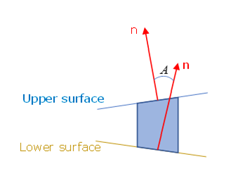

      Figure 3.
    • Parameter α MathType@MTEF@5@5@+= feaagKart1ev2aaatCvAUfeBSjuyZL2yd9gzLbvyNv2CaerbuLwBLn hiov2DGi1BTfMBaeXatLxBI9gBaerbd9wDYLwzYbItLDharqqtubsr 4rNCHbGeaGqiVu0Je9sqqrpepC0xbbL8F4rqqrFfpeea0xe9Lq=Jc9 vqaqpepm0xbba9pwe9Q8fs0=yqaqpepae9pg0FirpepeKkFr0xfr=x fr=xb9adbaqaaeGaciGaaiaabeqaamaabaabaaGcbaGaeqySdegaaa@3795@ is the scale factor used to describe the moment effect (like in the peeling test).
    • Parameter β could be fitted with normal and shear combined test. Like the 60° test or the 30° test.
      At least one combined test is needed to fit the parameter β . Figure 4 shows the effect of β on maximum stress in the combined test.
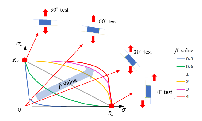

      Figure 4.
  6. The height of the solid element can be equal to zero. The element height does not affect the time step. Only nodal time step is available for this material.
  7. All nodes of the solid elements must be connected to other shells or solid elements, secondary nodes of rigid body (/RBODY) or secondary nodes of tied interface (/INTER/TYPE2).
  8. When all nodes of the solid element become free, the element is deleted.
  9. The rupture criteria for this material is defined by /FAIL/SNCONNECT.
  10. The true stress will be taken from fct_ID1 as:(3)
    Y = Y _ s c a l e 1 f 1 ( X X _ s c a l e 1 )

    With, f 1 being the function of fct_ID1