/PROP/TYPE43 (CONNECT)
Block Format Keyword This property is compatible with 8-noded hexahedron elements (/BRICK) only and may only be used with /MAT/LAW59 (CONNECT) and /MAT/LAW83 material laws. It is designed for spotweld, welding line or glue type connections.
Format
| (1) | (2) | (3) | (4) | (5) | (6) | (7) | (8) | (9) | (10) |
|---|---|---|---|---|---|---|---|---|---|
| /PROP/TYPE43/prop_ID/unit_ID or /PROP/CONNECT/prop_ID/unit_ID | |||||||||
| prop_title | |||||||||
| Ismstr | True_thickness | ||||||||
Definitions
| Field | Contents | SI Unit Example |
|---|---|---|
| prop_ID | Property
identifier. (Integer, maximum 10 digits) |
|
| unit_ID | Unit Identifier. (Integer, maximum 10 digits) |
|
| prop_title | Property
title. (Character, maximum 100 characters) |
|
| Ismstr | Strain formulation flag.
(Integer) |
|
| True_thickness | Overwrites the thickness
of the solid element. (Real) |
Comments
- The element with this property is designed to be connected to other shells or solid elements. Its nodes may also be secondary of a rigid body (/RBODY) or secondary nodes of kinematic tied interface (/INTER/TYPE2).
- Orientation of the
elementThe orientation of the element normal direction (t-axis) is different than a typical solid element and instead is similar to a shell element. The normal direction t is constructed from bottom (nodes 1-2-3-4) to the top (nodes 5-6-7-8). Due to this difference, pre-processors will show the element normal of connection elements in s-axis direction which corresponds to the typical solid element.
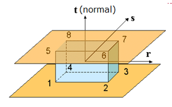
Figure 1.The element local coordinate system is constructed in the mid-plane section between the bottom (1-2-3-4) and top (5-6-7-8) faces.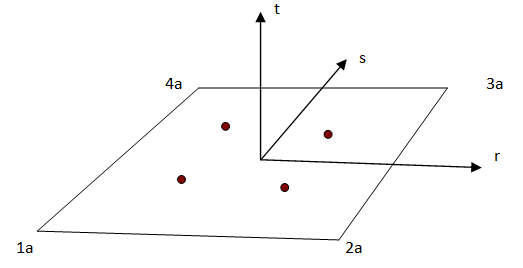
Figure 2.The element has four Gauss integration points placed in the mid-plane section defined by points 1a, 2a, 3a, and 4a. These four points (1a, 2a, 3a, and 4a) lie midway between the bottom and top face nodes, and the orientation of the local coordinate axes (r-s-t) is the same as that of shell elements and t-axis is assume to be directed from bottom face to top face.
- Time step
- The height of the solid element (length in local t direction) can be zero. This length will not affect the time step.
- But if several nodes of element are independent/disconnected, one must pay attention to the resulting time step, especially if the element has null or small height and/or mass density. It may result on very small or null nodal time step.
The element does not compute its own time step. The stability is assured by nodal time step in every case (even if elementary time step is generally used).
- When using the automatic setting option Ismstr = Icpre = Iframe=-1, the values for these options are defined using the best options based on the element formulation, element type, and material. Alternatively, defining Ismstr = Icpre = Iframe=-2 will overwrite the values for these options defined in this property with the best value based on element type and material law. To see the values defined by Radioss, review the “PART ELEMENT/MATERIAL PARAMETER REVIEW” section of the Starter output file.
- Ismstr – small strain
formulation
If Ismstr=0 in /PROP/TYPE43, the Ismstr value depends on what Ismstr is defined in /DEF_SOLID (see below).
Ismstr=10 is the total strain, which is not supported by /PROP/TYPE43, so here Ismstr=4 is used.Ismstr in /PROP/TYPE43 Ismstr in /DEF_SOLID Ismstr used by /PROP/TYPE43 Ismstr=0 Ismstr=0 Ismstr=1 Ismstr=1 Ismstr=1 Ismstr=2 Ismstr=1 Ismstr=3 Ismstr=1 Ismstr=4 Ismstr=4 Ismstr=10 Ismstr=4 - By default, the thickness of the element is the height of the solid element in the t direction. If the solid elements are used to connect shells elements, the solid element height will not be physically correct, due to the shell elements thickness. Therefore, a reduced solid element thickness can be defined using True_thickness.
- Model instabilities can occur if True_thickness is larger than the thickness of the solid element in the model.