Connect Materials (LAW59)
For the moment /MAT/LAW59 is only compatible with /PROP/TYPE43 and /FAIL/CONNECT.
Solid Connection Element and Material
These materials and properties are only compatible with each other; /FAIL/CONNECT, and the designated failure model.
They are designed for spotweld, welding line or glue type connections.
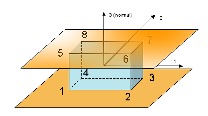
Figure 1. Solid Connect Element
The main characteristic of CONNECT property is the time step is independent on the element height, only on the section surface area. Hence, it can be used for glue or spotweld connections, with null height distance.
Element Definition
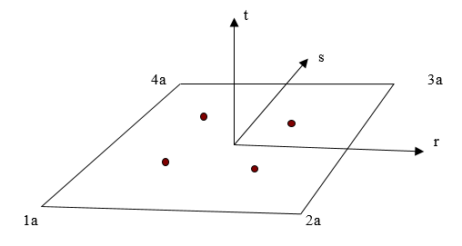
Figure 2. Points 1a, 2a, 3a and 4a are in the Mid Distance between Bottom and Top Face Nodes
The local element system is fully corotational (not only convected), local deformations are thus independent on rigid element rotations.
Dzz = sum(Ni*Vzi)i=5,6,7,8 - sum(Nj*Vzj)j=1,2,3,4
Dxz = sum(Ni*Vxi)i=5,6,7,8 - sum(Nj*Vxj)j=1,2,3,4
Dyz = sum(Ni*Vyi)i=5,6,7,8 - sum(Nj*Vyj)j=1,2,3,4- Vx, Vy, and Vz
- Nodal velocities in local corotational system
- Ni
- Function forms
The element has only three "strain" components - traction/compression in normal (Z) direction and both transverse shears XZ and YZ. Actually, in-plane shear, as well as lateral tractions/compressions does not give any resistance forces. It's a pure "connection" element and is not intended to be used in independent way. Both upper and bottom faces have to be tied to different structural parts.
Material Law
The elastic-plastic behavior is modeled independently in normal and tangent (in-plane) directions in each Gauss integration points, using user-defined functions for work hardening curve. There is no coupling between normal and shear direction in the material law. The hardening model is purely isotropic. Different number of hardening curves may be defined in each direction, for different values of deformation rate.
For a given strain rate, a linear interpolation between corresponding curves is used to find the value of the yield stress for the actual plastic displacement.
Deformation rates may be optionally filtered. In this regard, the law is similar to the classical elastic-plastic tabulated approach.
Nodal forces are assembled using stress components calculated in each Gauss integration point, and additional treatment is performed to assure global force and moment balance at every time step.
Input Parameters
The material stiffness parameters are input as total element rigidity per section area, which is equivalent to the Young and shear modulus per height unit ( ).
The hardening functions are expressed as engineering stress relative to plastic displacements.
Element Stability
The element does not have its own elementary time step. Corresponding nodal time step is calculated using nodal masses and stiffness to assure the numerical stability. In Radioss v12.0, the nodal time step is imposed to the whole model, in the next releases the elementary time step is option is maintained if chosen in the Engine input file, only the connection material elements will use nodal time step.