Finite Element Formulation

Finite Element Approximation

In the finite element method, the motion x ( X , t ) is approximated by:(1) x i ( X , t ) = Φ I ( X ) x i I ( t )
Where,
Φ I ( X )
Interpolating shape functions
x i I
Position vector of node I MathType@MTEF@5@5@+= feaagKart1ev2aaatCvAUfeBSjuyZL2yd9gzLbvyNv2CaerbuLwBLn hiov2DGi1BTfMBaeXatLxBI9gBaerbd9wDYLwzYbItLDharqqtubsr 4rNCHbGeaGqiVu0Je9sqqrpepC0xbbL8F4rqqrFfpeea0xe9Lq=Jc9 vqaqpepm0xbba9pwe9Q8fs0=yqaqpepae9pg0FirpepeKkFr0xfr=x fr=xb9adbaqaaeGaciGaaiaabeqaamaabaabaaGcbaGaamysaaaa@36C4@
Summation over repeated indices is implied. In the case of lower indices, summation is over the number of space dimensions. For upper case indices, summation is over the number of nodes. The nodes in the sum depend on the type of entity considered. When the volume is considered, the summation is over all the nodes in the domain. When an element is considered, the sum is over the nodes of the element.
Similarly, nodal displacements are defined using Material and Spatial Coordinates, Equation 2 at nodes:(2) u i I ( X , t ) = x i I ( t ) X i I
The displacement field is:(3) u i ( X , t ) = Φ I ( X ) u i I ( t )
The velocities are obtained by taking the material time derivative of the displacement giving:(4) v i ( X , t ) = u i ( X , t ) t = Φ I ( X ) v i I ( t )

It is worth pointing out that the velocity is a material time derivative of displacements, i.e. the partial derivative with respect to time with the material coordinate fixed.

Finally, accelerations are similarly given by the material time derivative of velocities:(5) v ˙ i ( X , t ) = Φ I ( X ) v ˙ i I ( t )

Emphasis is placed on the fact that shapes functions are functions of the material coordinates whatever the updated or the total Lagrangian formulation is used. All the dependency in the finite element approximation of the motion is taken into account in the values of the nodal variables.

From Kinematic Description, Equation 8, the velocity gradient is given by:(6) L i j = v i x j = v i I Φ I x j = v i I Φ I , j
and the rate of deformation (Kinematic Description, Equation 14) by:(7) D i j = 1 2 ( L i j + L j i ) = 1 2 ( v i I Φ I , j + v j I Φ I , i )
Similarly, the test functions are approximated as:(8) δ v i ( X ) = Φ I ( X ) δ v i I

Where, δ v i I are the virtual nodal velocities.

The test functions are next substituted into the principle of virtual power (Virtual Power Principle, Equation 5) giving:(9) δ v i I Ω Φ I x j σ j i d Ω δ v i I Ω Φ I ρ b i d Ω δ v i I Γ σ Φ I τ i d Γ + δ v i I Ω Φ I ρ v ˙ i d Ω = 0
The virtual velocities must be kinematically admissible, that is, satisfy boundary conditions on Γ u , the part of the boundary where kinematical conditions are specified. Using the arbitrariness of the virtual nodal velocities everywhere except on Γ u , the weak form of the momentum equation is:(10) Ω Φ I x j σ j i d Ω Ω Φ I ρ b i d Ω Γ σ Φ I τ i d Γ + Ω Φ I ρ v ˙ i d Ω = 0

with Γ σ the part of the boundary where traction loads are imposed.

Internal and External Nodal Forces

As in Virtual Power Term Names, you define the nodal forces corresponding to each term in the virtual power equation.

The internal nodal forces are defined by:(11) δ P int = δ v i I f i I int = Ω δ v i x j σ j i d Ω = δ v i I Ω Φ I x j σ j i d Ω
The stress is the true (Cauchy) stress.(12) f i I int = Ω σ j i ( Φ I x j ) d Ω

These nodal forces are called internal because they represent the stresses in the body. The expression applies to both the complete mesh or to any element. It is pointed out that derivatives are taken with respect to spatial coordinates and that integration is taken over the current deformed configuration.

The external forces are similarly defined in terms of the virtual external power:(13) δ P e x t = δ v i I f i I e x t = δ v i l Ω Φ I ρ b i d Ω + δ v i l Γ σ Φ I τ i d Γ
so that external forces are given by:(14) f i I e x t = Ω Φ I ρ b i d Ω + Γ σ Φ I τ i d Γ

Mass Matrix and Inertial Forces

The inertial body forces are defined by:(15) δ P i n e r t = δ v i I f i I i n e r t = δ v i I Ω Φ I ρ v ˙ i d Ω = δ v i I Ω Φ I ρ v ˙ i d Γ
so that the inertia forces are given by:(16) f i I i n e r t = Ω Φ I ρ v ˙ i d Ω
or using the Finite Element Approximation, Equation 5 for the accelerations:(17) f i I i n e r t = Ω ρ Φ I Φ J d Ω v ˙ i J
It is usual to define the inertial nodal forces as the product of a mass matrix and the nodal accelerations. Defining the mass matrix as:(18) M i j I J = δ i j Ω ρ Φ I Φ J d Ω
the inertial forces are given by:(19) f i I i n e r t = M i j I J v ˙ j J

Discrete Equations

Using the definitions of the internal and external forces, as well as the definition of the inertial forces, it is possible to write the weak form of the virtual power principle as:(20) δ v i I ( M i j I J v ˙ j J + f i I int f i I e x t ) = 0
or taking into account the arbitrariness of the virtual velocities:(21) M i j I J v ˙ j J + f i I int = f i I e x t

Equation of Motion for Translational Velocities

Discrete Equations, Equation 21 is written in matrix notation as:(22) M d v d t = f e x t f int
This is Newton's equation, where the mass matrix is:(23) M = Ω ρ Φ T Φ d Ω
Radioss uses a lumped mass approach, i.e. each node represents a discrete mass of zero size. This creates a diagonal mass matrix M MathType@MTEF@5@5@+= feaagKart1ev2aaatCvAUfeBSjuyZL2yd9gzLbvyNv2CaerbuLwBLn hiov2DGi1BTfMBaeXatLxBI9gBaerbd9wDYLwzYbItLDharqqtubsr 4rNCHbGeaGqiVu0Je9sqqrpepC0xbbL8F4rqqrFfpeea0xe9Lq=Jc9 vqaqpepm0xbba9pwe9Q8fs0=yqaqpepae9pg0FirpepeKkFr0xfr=x fr=xb9adbaqaaeGaciGaaiaabeqaamaabaabaaGcbaGaamiBaaaa@36E7@ , eliminating, as you will see in Dynamic Analysis, the need to solve simultaneous equations for the solution of nodal accelerations.(24) f e x t = Γ Φ T τ d Γ + Ω ρ Φ T b d Ω
is the externally applied load vector, and the internal force vector is:(25) f i I int = Ω σ i j Φ I x j d Ω
Adding to the internal and external forces the anti-hourglass force vector and the contact force vector which will be described in the following sections, you obtain the overall equation of motion:(26) M d v d t = f e x t f int + f h g r + f c o n t

Equation of Motion for Angular Velocities

Shell, beam and rigid body theory introduces nodal rotational degrees of freedom. The equations of motion for rotational degrees of freedom are complicated if written in the global reference frame. They are much simpler if written for each node in the principal reference frame attached to the node. The resulting equations are the standard Euler equations. They are completely analogous to Newton's law governing translational degrees of freedom and are stated as:(27) l 1 α 1 + ( I 3 I 2 ) ω 2 ω 3 = m 1 e x t m 1 int (28) l 2 α 2 + ( I 1 I 3 ) ω 1 ω 3 = m 2 e x t m 2 int (29) l 3 α 3 + ( I 2 I 1 ) ω 1 ω 2 = m 3 e x t m 3 int
Where,
I 1 , I 2 , I 3
Principal moments of inertia about the x, y and z axes respectively
α 1 , α 2 , α 3
Angular accelerations expressed in the principal reference frame
ω 1 , ω 2 , ω 3
Angular velocities
m 1 e x t , m 2 e x t , m 3 e x t
Principal externally applied moments
m 1 int , m 2 int , m 3 int
Principal internal moments
The equation of motion for rotational degrees of freedom is thus very similar to that for translational degrees of freedom. In matrix notation and in the nodal principal reference frame:(30) I d ω d t = M e x t M int + F ( ω )

The vector function F ( ω ) is computed for a value of ω at t δ t / 2 . Equation 30 is used for rigid body motion.

For shell, beam and spring using a spherical inertia, the equation of motion becomes:(31) I d ω d t = M e x t M int + M h g r
Where,
I = e l e m e n t s I e
Diagonal inertia matrix
M e x t = e l e m e n t s m e x t
Externally applied moment vector
M int = e l e m e n t s m int
Internal moment vector
M h g r = s h e l l s m h g r
Anti-hourglass shell moment vector

Element Coordinates

Finite elements are usually developed with shape functions expressed in terms of an intrinsic coordinates system ξ , η , ζ . It is shown hereafter that expressing the shape functions in terms of intrinsic coordinates is equivalent to using material coordinates.

When an element is treated in terms of intrinsic coordinates, we are concerned with three domains that correspond to this element:
  • The domain in the intrinsic coordinates system
  • The current element domain
  • The initial reference element domain

ξ is associated with the direction u MathType@MTEF@5@5@+= feaagKart1ev2aaatCvAUfeBSjuyZL2yd9gzLbvyNv2CaerbuLwBLn hiov2DGi1BTfMBaeXatLxBI9gBaerbd9wDYLwzYbItLDharqqtubsr 4rNCHbGeaGqiVu0Je9sqqrpepC0xbbL8F4rqqrFfpeea0xe9Lq=Jc9 vqaqpepm0xbba9pwe9Q8fs0=yqaqpepae9pg0FirpepeKkFr0xfr=x fr=xb9adbaqaaeGaciGaaiaabeqaamaabaabaaGcbaGaamyDaaaa@36F0@

η is associated with the direction v MathType@MTEF@5@5@+= feaagKart1ev2aaatCvAUfeBSjuyZL2yd9gzLbvyNv2CaerbuLwBLn hiov2DGi1BTfMBaeXatLxBI9gBaerbd9wDYLwzYbItLDharqqtubsr 4rNCHbGeaGqiVu0Je9sqqrpepC0xbbL8F4rqqrFfpeea0xe9Lq=Jc9 vqaqpepm0xbba9pwe9Q8fs0=yqaqpepae9pg0FirpepeKkFr0xfr=x fr=xb9adbaqaaeGaciGaaiaabeqaamaabaabaaGcbaGaamyDaaaa@36F0@

ς is associated with the direction w MathType@MTEF@5@5@+= feaagKart1ev2aaatCvAUfeBSjuyZL2yd9gzLbvyNv2CaerbuLwBLn hiov2DGi1BTfMBaeXatLxBI9gBaerbd9wDYLwzYbItLDharqqtubsr 4rNCHbGeaGqiVu0Je9sqqrpepC0xbbL8F4rqqrFfpeea0xe9Lq=Jc9 vqaqpepm0xbba9pwe9Q8fs0=yqaqpepae9pg0FirpepeKkFr0xfr=x fr=xb9adbaqaaeGaciGaaiaabeqaamaabaabaaGcbaGaamyDaaaa@36F0@

The motion in each element can thus be described by the composition of three maps (the reasoning is described only for the direction u MathType@MTEF@5@5@+= feaagKart1ev2aaatCvAUfeBSjuyZL2yd9gzLbvyNv2CaerbuLwBLn hiov2DGi1BTfMBaeXatLxBI9gBaerbd9wDYLwzYbItLDharqqtubsr 4rNCHbGeaGqiVu0Je9sqqrpepC0xbbL8F4rqqrFfpeea0xe9Lq=Jc9 vqaqpepm0xbba9pwe9Q8fs0=yqaqpepae9pg0FirpepeKkFr0xfr=x fr=xb9adbaqaaeGaciGaaiaabeqaamaabaabaaGcbaGaamyDaaaa@36F0@ ):
  • The map from the intrinsic coordinates system to the initial configuration:
    (32) X ( ξ )
  • The map from the intrinsic coordinates system to the current configuration:
    (33) x ( ξ , t )
  • The map from the initial to the current configuration:
    (34) x = ϕ ( X , t )
So, it is possible to approximate the motion in an element by:(35) x i ( ξ , t ) = Φ I ( ξ ) x i I ( t )
Shape functions Φ I ( ξ ) have no dimensions. They simply relate coordinates in the physical world to the intrinsic coordinates system. Writing Equation 35 at t MathType@MTEF@5@5@+= feaagKart1ev2aaatCvAUfeBSjuyZL2yd9gzLbvyNv2CaerbwvMCKf MBHbqefqvATv2CG4uz3bIuV1wyUbqedmvETj2BSbqefm0B1jxALjhi ov2DaebbnrfifHhDYfgasaacH8srps0lbbf9q8WrFfeuY=Hhbbf9v8 qqaqFr0xc9pk0xbba9q8WqFfea0=yr0RYxir=Jbba9q8aq0=yq=He9 q8qqQ8frFve9Fve9Ff0dmeaacaGacmGadaWaaiqacaabaiaafaaake aacaWGIbaaaa@39BE@ =0, you obtain:(36) x i ( ξ ) = x i ( ξ , 0 ) = Φ I ( ξ ) x i I ( 0 ) = Φ I ( ξ ) x i I
So, it can be seen from the last equation that the material coordinates system and the intrinsic coordinates system are invariant in a Lagrangian element. As a result, as intrinsic coordinates are time invariant and it is possible to write displacements, velocities and accelerations in terms of intrinsic coordinates (one coordinate system, the two other coordinates have similar shape functions):(37) u i ( ζ , t ) = Φ I ( ξ ) u i I ( t ) (38) u ˙ i ( ζ , t ) = Φ I ( ξ ) u ˙ i I ( t ) (39) v ˙ i ( ζ , t ) = Φ I ( ξ ) v ˙ i I ( t )

Isoparametric elements use the same shape functions for the interpolation of x , u , u ˙ and v ˙ .

Integration and Nodal Forces

In practice, integrals over the current domain in the definition of the internal nodal forces (Equation of Motion for Translational Velocities, Equation 25), of the external nodal forces (Equation of Motion for Translational Velocities, Equation 24) and of the mass matrix have to be transformed into integrals over the domain in the intrinsic coordinate system Δ .

Using Vicinity Transformation, Equation 5, integrals on the current configuration are related to integrals over the reference configuration and over the domain in the intrinsic coordinate system by:(40) Ω g ( x ) d Ω = Ω 0 g ( x ) | F | d Ω 0 = Δ g ( ξ ) | F ξ | d Δ
and(41) Ω 0 g ( X ) d Ω 0 = Δ g ( ξ ) | F ξ 0 | d Δ
Where,
| F |
The Jacobian determinant of the transformation between the current and the initial configuration
| F ξ |
The Jacobian determinant of the transformation between the current configuration and the domain in the intrinsic coordinate system
| F ξ 0 |
The Jacobian determinant of the transformation between the reference configuration and the intrinsic coordinate system
On the other hand, it comes from Vicinity Transformation, Equation 2 and Element Coordinates, Equation 35:(42) F ξ k j = x k ξ j = Φ I ( ξ ) ξ j x k l
So, using Equation 40, internal forces computed by integration over the current domain will be obtained by the following quadrature:(43) f i I int = Ω σ i j Φ I x j d Ω = Δ σ i j Φ I x j | F ξ | d Δ

and | F ξ | obtained from Equation 42.

External forces and the mass matrix can similarly be integrated over the domain in the intrinsic coordinate system.

Function Derivatives

The definition of internal forces also shows that derivatives of the form:(44) x j
need to be computed. These spatial derivatives are obtained by implicit differentiation. Considering the velocity gradient such as:(45) L i j = v i x j
one has:(46) L i j = v i ξ k ξ k x j = v i ξ k F ξ k j 1 = v i I Φ I ξ k F ξ k j 1
Where, the Jacobian matrix of the map between the current coordinates and the intrinsic coordinates is:(47) F ξ k j = x k ξ j = Φ I ( ξ ) ξ j x k I

Usually, it is not possible to have closed form expression of the Jacobian matrix. As a result the inversion will be performed numerically and numerical quadrature will be necessary for the evaluation of nodal forces.

Numerical Quadrature: Reduced Integration

All elements in Radioss are integrated numerically. Hence, the integrals for nodal forces are replaced by a summation:(48) f ( ξ ) d ξ = j = 1 n w j f ( ξ j )
Where,
n MathType@MTEF@5@5@+= feaagKart1ev2aaatCvAUfeBSjuyZL2yd9gzLbvyNv2CaerbuLwBLn hiov2DGi1BTfMBaeXatLxBI9gBaerbd9wDYLwzYbItLDharqqtubsr 4rNCHbGeaGqiVu0Je9sqqrpepC0xbbL8F4rqqrFfpeea0xe9Lq=Jc9 vqaqpepm0xbba9pwe9Q8fs0=yqaqpepae9pg0FirpepeKkFr0xfr=x fr=xb9adbaqaaeGaciGaaiaabeqaamaabaabaaGcbaGaamOBaaaa@36E9@
Number of integration points in the element
w j
Eeight associated to the integration point j MathType@MTEF@5@5@+= feaagKart1ev2aaatCvAUfeBSjuyZL2yd9gzLbvyNv2CaerbuLwBLn hiov2DGi1BTfMBaeXatLxBI9gBaerbd9wDYLwzYbItLDharqqtubsr 4rNCHbGeaGqiVu0Je9sqqrpepC0xbbL8F4rqqrFfpeea0xe9Lq=Jc9 vqaqpepm0xbba9pwe9Q8fs0=yqaqpepae9pg0FirpepeKkFr0xfr=x fr=xb9adbaqaaeGaciGaaiaabeqaamaabaabaaGcbaGaamOBaaaa@36E9@
Values of w j and locations of ξ j are given in tables according to the numerical quadrature approach. Radioss uses either full or reduced integration schemes.

For full integration, the number of integration points is sufficient for the exact integration of the virtual work expression. The full integration scheme is often used in programs for static or dynamic problems with implicit time integration. It presents no problem for stability, but sometimes involves locking and the computation is often expensive.

Reduced integration can also be used. In this case, the number of integration points is sufficient for the exact integration of the contributions of the strain field that are one order less than the order of the shape functions. The incomplete higher order contributions to the strain field present in these elements are not integrated.

The reduced integration scheme, especially with one-point quadrature is widely used in programs with explicit time integration to compute the force vectors. It drastically decreases the computation time, and is very competitive if the spurious singular modes (often called hourglass modes which result from the reduced integration scheme) are properly stabilized. In two dimensions, a one point integration scheme will be almost four times less expensive than a four point integration scheme. The savings are even greater in three dimensions. The use of one integration point is recommended to save CPU time, but also to avoid "locking" problems, e.g. shear locking or volume locking.

Shear locking is related to bending behavior. In the stress analysis of relatively thin members subjected to bending, the strain variation through the thickness must be at least linear, so constant strain first order elements are not well suited to represent this variation, leading to shear locking. Fully integrated first-order isoparametric elements (tetrahedron) also suffer from shear locking in the geometries where they cannot provide the pure bending solution because they must shear at the numerical integration points to represent the bending kinematic behavior. This shearing then locks the element, that is, the response is far too stiff.

On the other hand, most fully integrated solid elements are unsuitable for the analysis of approximately incompressible material behavior (volume locking). The reason for this is that the material behavior forces the material to deform approximately without volume changes. Fully-integrated solid elements, and in particular low-order elements do not allow such deformations. This is another reason for using selectively reduced integration. Reduced integration is used for volume strain and full integration is used for the deviatoric strains.

However, as mentioned above, the disadvantage of reduced integration is that the element can admit deformation modes that are not causing stresses at the integration points. These zero-energy modes make the element rank-deficient which causes a phenomenon called hour-glassing; the zero-energy modes start propagating through the mesh, leading to inaccurate solutions. This problem is particularly severe in first-order quadrilaterals and hexahedra.

To prevent these excessive deformations, a small artificial stiffness or viscosity associated with the zero-energy deformation modes is added, leading in Equation of Motion for Translational Velocities, Equation 22 and Equation of Motion for Angular Velocities, Equation 30 to anti-hourglass force and moment vectors:(49) M d v d t = f e x t f int + f h g r (50) I d ω d t = M e x t M int + M h g r

Zero-energy or hourglass modes are controlled using a perturbation stabilization as described by Flanagan-Belytschko 1, or physical stabilization as described in 2 (Element Library).

So, for isoparametric elements, reduced integration allows simple and cost effective computation of the volume integrals, in particular on vectorized supercomputers, and furnishes a simple way to cope with locking aspects, but at the cost of allowing hour-glassing.

Numerical Procedures

The Radioss numerical solver can be summarized by the flow chart in Figure 1. For each time step in a particular analysis, the algorithm used to compute results is:
  1. For the displacement, velocity and acceleration at a particular time step, the external force vector is constructed and applied.
  2. A loop over element is performed, in which the internal and hourglass forces are computed, along with the size of the next time step. The procedure for this loop is:
    1. The Jacobian matrix is used to relate displacements in the intrinsic coordinates system to the physical space:
      (51) Φ x j | t = F ξ 1 Φ ξ | t
    2. The strain rate is calculated:
      (52) ε ˙ i j = ( Φ I x j ) x ˙ = 1 2 ( v i x j + v j x i )
    3. The stress rate is calculated:
      (53) σ ˙ i j = f ( ε ˙ , m a t e r i a l l a w )
    4. Cauchy stresses are computed using explicit time integration: (54) σ ( t + Δ t ) = σ ( t ) + σ ˙ Δ t
    5. The internal and hourglass force vectors are computed.
    6. The next time step size is computed, using element or nodal time step methods (Dynamic Analysis)
  3. After the internal and hourglass forces are calculated for each element, the algorithm proceeds by computing the contact forces between any interfaces.
  4. With all forces known, the new accelerations are calculated using the mass matrix and the external and internal force vectors: (55) v ˙ i = M 1 ( f e x t i f int i )
  5. Finally, time integration of velocity and displacement is performed using the new value.


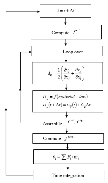
    Figure 1. Numerical Procedure
1 Flanagan D. and Belytschko T., “A Uniform Strain Hexahedron and Quadrilateral with Orthogonal Hourglass Control”, Int. Journal Num. Methods in Engineering, 17 679-706, 1981.
2 Zeng Q. and Combescure A., “A New One-point Quadrature, General Nonlinear Quadrilateral Shell Element with Physical Stabilization”, Int. Journal Num. Methods in Engineering 42, 1307-1338, 1998.