Materials/Failure
Hashin failure info in Engine output file
When using /FAIL/HASHIN + /PROP/TSH_COMP + Isolid=14, the number of integration points listed as "FAILURE LAYER" in the Engine output file depends on the integration points defined in your property.
Example:
FAILURE LAYER # 11 ELEMENT # 1763 HASHIN MODE # 6 AT TIME #: 3.6405803218587E-0
The correspondence between the number of integration points, ijk, and the number of "FAILURE LAYER" in the output file depends on your property description. How many integration points each plane define and how many layers through the thickness are defined in your property.
- FAILURE LAYER # 1 ~ FAILURE LAYER # 8 means all integration points through layers in position of 1st integration point in plane
- FAILURE LAYER # 9 ~ FAILURE LAYER # 16 means all integration points through layers in position of 2nd integration point in plane.
- FAILURE LAYER # 17 ~ FAILURE LAYER # 24 means all integration points through layers in position of 3rd integration point in plane.
- FAILURE LAYER # 25 ~ FAILURE LAYER # 32 means all integration points
through layers in position of 4th integration point in plane.
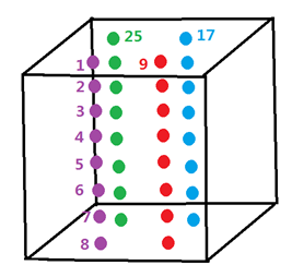
Figure 1.
LAW24 material parameters
- Density by weighing a specimen
- Young's modulus from a cylinder compression test
- Poisson coefficient is usually assumed to be near 0.2
- Compression strength, 'fc' from a cube compression test
- Get ‘ft’ from tensile
test:
‘ft’ is direct tensile strength. This test provides ‘ft/fc’ value for LAW24.
- Get couple of (fst,
Ht) from Splitting tensile test:
This test is also called "Brazilian test".
‘fst’ is splitting tensile strength in Splitting tensile test. It is asssumed that ft=0.71fst. Then you need to model this test to fit failure limit by validating ‘Ht’ value. Isolid=24 is also recommended for solid property for in Splitting tensile test.
- Get ‘fb’ from Biaxial test and get (f2,s0) from confined test.
It is always recommended to use the default value in LAW24, if no test data supported.
Refer to RD-E: 4701 Concrete Validation with Kupfer Tests for more information.
Stress/Strain Input
For elastic plastic laws in Radioss, the function defines the true stress versus the plastic true strain which can be obtained by converting the experimental tensile test curve. Refer to RD-E: 1100 Tensile Test for details
For some other laws that are not elastic plastic such as /MAT/LAW38 (VISC_TAB), /MAT/LAW69, /MAT/LAW70 (FOAM_TAB), and /MAT/LAW90, an engineering stress versus engineering strain curve is used.
Warnings ID's 519 and 520
WARNING ID: 519
** WARNING IN SANDWICH SHELL INITIALIZATION
SHELL (ID=…) MASS (TYPE NUMBER …)
SUM OF LAYER MASS DIFFER FROM TOTAL
WARNING ID: 520
** WARNING IN SANDWICH SHELL INITIALIZATION
SHELL (ID=…) INERTIA (TYPE NUMBER …)
POTENTIAL INSTABILITY DUE TO LAYER INERTIA DISTRIBUTION
Due to improvements in Radioss v14, these warning will no longer occur. For older versions of Radioss, the warning comes from a shell element using a /PROP/TYPE11 (SH_SANDW).
They mean that the mass (or inertia) of the shell, as it is computed from the characteristics of each layer (position, thickness, associated material), is not equal to the mass (or inertia) which is computed from the global material associated to the PART and the total thickness of the shell given in the property TYPE11.
- Area of shell element
- Number of layers
- Density of layer
- Thickness of layer
- Distance to the middle plane of the shell element
The stability time step is computed from the global characteristics of the shell; it cannot be ensured if the mass and inertia computed for the shell are not close enough to the mass and inertia which is computed from the density of the global material and the total thickness given in the shell property. So these messages are written if the relative error with respect to the mass (or inertia) computed from the global characteristics is greater than 1%.
In order to ensure the stability, it is recommended to set a Young's modulus for the global material, at least equal to the maximum modulus of the materials associated to all layers.
Failure output for LAW25
- FAILURE-1
- Criteria for maximum tensile strain in first direction has been reached
- FAILURE-2
- Criteria for maximum tensile strain in second direction has been reached
- FAILURE-P
- Criteria (maximum plastic work for failure) has been reached
In any case, the concerned element identifier and the number of the layer that has failed are written.
RUPTURE OF SHELL ELEMENT …
Solid element deletion and plastic strain failure
When failure is defined in a material law using the maximum plastic strain the deletion of the element depends on the material law.
For Material Laws 2, 4 and 22, only the deviatoric part of the stress tensor is set to zero, the internal pressure of the solid is still computed and the element is not deleted.
For Material Laws 3, 23, 28 and 36 the solid elements are deleted when is reached.
Beam element failure deletion
The maximum strain failure criteria in LAW36 and LAW2 does not work with beam elements because the total strain in beam elements is not calculated. This makes any failure criteria based on maximum strain not compatible with beams.
Global integration
If number of integration points N=0 in /PROP/SHELL, then global integration approach is used.
For elasto-plastic laws, global integration requires that yield criteria of plasticity be written with resultant stresses. The advantage is reduced computational cost which is similar to using N=3.
The disadvantage is the same material behavior is done throughout the thickness (especially for loading and unloading).
For simple load cases you can still get good results with less computation times by using the global integration approach.
For complicated load cases where loading and unloading happened differently throughout thickness, the precision of results might not be accurate enough when using the global integration approach.
- Global integration (N=0) is only compatible with Material Laws 1, 2, 22, 36, 43 and 60.
- Failure models are not available with global integration for shells.
- Global integration is not compatible with saving stresses to state files using /STATE/DT which creates /INISHE and /INISH3N.
Therefore, is it not recommended to use global integration; but, instead to specify N=5 integration points though the thickness.
Up to V44, material LAW1 for shells does not use integration points but switches to the global formulation (corresponding to N=0); whatever the number of integration points N is asked for.
So up to V44, there is no way to use this material law with only one integration point and membrane only behavior.
Now, LAW1 is only available for global integration (N=0 or N > 1 in /PROP/SHELL) and membrane formulations (with NP=1 in /PROP/SHELL). Global integration option (N=0 in Radioss) directly computes the resultant stresses (F1, F2, F12, M1, M2, and M12) without considering the integration throughout thickness numerically (with classic strain, stress), so there is no value for SX_JJ, SY_JJ, SXY_JJ, SYZ_JJ, SZX_JJ with JJ=1,99 in /TH/SHELL. (Refer to How is the generalized stress tensor /ANIM/SHELL/TENS/MEMB and /ANIM/SHELL/TENS/BEND computed? in FAQs). The default value for Iplas in case of LAW2 and global integration (N=0 in shell property) is Iplas =2: radial return.
The default value for Iplas in case of LAW36 and global integration (N=0 in shell property) is Iplas =1: iterative projection.
Non-reflecting Eulerian boundary condition
- /MAT/LAW51: Iform=6 for multi-material modeling.
- /MAT/LAW11 – Iform=3 or /EBCS (GRADP0,…) for mono-material modeling.
Usually, only a few parameter definitions are needed.
The results will be better if the convection direction of the mesh is created normal to the element face shared with the boundary element.