/PROP/TYPE11 (SH_SANDW)
Block Format Keyword This property set is used to define the sandwich shell property set. It is possible to define sandwich composite with several layers and each lay with individual material, thickness, layer position and orthotropic direction.
This property is only compatible with Material Laws 15, 25, 27, 36, 60, 72 and user laws and is compatible with XFEM (crack propagation) using /FAIL/JOHNSON, /FAIL/TAB1 and /FAIL/TBUTCHER.
Format
| (1) | (2) | (3) | (4) | (5) | (6) | (7) | (8) | (9) | (10) |
|---|---|---|---|---|---|---|---|---|---|
| /PROP/TYPE11/prop_ID/unit_ID or /PROP/SH_SANDW/prop_ID/unit_ID | |||||||||
| prop_title | |||||||||
| Ishell | Ismstr | Ish3n | Idril | P_thickfail | |||||
| hm | hf | hr | dm | dn | |||||
| N | Istrain | Thick | Ashear | Ithick | Iplas | ||||
| VX | VY | VZ | Skew_ID | Iorth | Ipos | ||||
| (1) | (2) | (3) | (4) | (5) | (6) | (7) | (8) | (9) | (10) |
|---|---|---|---|---|---|---|---|---|---|
| ti | Zi | mat_IDi | F_weighti | ||||||
Definitions
| Field | Contents | SI Unit Example |
|---|---|---|
| prop_ID | Property
identifier (Integer, maximum 10 digits) |
|
| unit_ID | Unit Identifier (Integer, maximum 10 digits) |
|
| prop_title | Property
title (Character, maximum 100 characters) |
|
| Ishell | Shell element formulation
flag. 1
(Integer) |
|
| Ismstr | Shell small strain
formulation flag. 2
(Integer) |
|
| Ish3n | 3 node shell element
formulation flag.
(Integer) |
|
| Idril | Drilling degree of freedom
stiffness flag. 8
(Integer) |
|
| P_thickfail | Percentage of layer
thickness that must fail before the element is deleted. 12
13
(Real) |
|
| hm | Shell membrane hourglass
coefficient. Default = 0.01 Default = 0.1 for hourglass type 3 (Ishell =3) (Real) |
|
| hf | Shell out-of-plane
hourglass. Default = 0.01 (Real) |
|
| hr | Shell rotation hourglass
coefficient. Default = 0.01 Default = 0.1 for hourglass type 3 (Ishell =3) (Real) |
|
| dm | Shell Membrane Damping. Default =0.0% Default =1.5% for Ishell =24 (QEPH)+LAW 27 Default =5.0% for Ishell =1,2,3,4,12+LAW25 and 27 (Real) |
|
| dn | Shell numerical damping.
4 It only used for Ishell =12 and 24 Default =1.5% for Ishell =24 (QEPH) Default =0.1% for Ishell =12 (QBAT) Default =0.01% for Ish3n =30 (DKT18) (Real) |
|
| N | Number of layers, with 1 ≤
N ≤ 100. Default = 1 (Integer) |
|
| Istrain | Compute strains for
post-processing flag.
(Integer) |
|
| Thick | Shell thickness. 10 (Real) |
|
| Ashear | Shear factor. Default is Reissner value: 5/6 (Real) |
|
| Ithick | Shell resultant stresses
calculation flag.
(Integer) |
|
| Iplas | Shell plane stress
plasticity flag.
(Integer) |
|
| VX | X component for reference
vector. Default = 1.0 (Real) |
|
| VY | Y component for reference
vector. Default = 0.0 (Real) |
|
| VZ | Z component for reference
vector. Default = 0.0 (Real) |
|
| Skew_ID | Skew identifier for
reference vector. 9 If the local skew is defined, its X-axis replaces the global vector . VX, VY, and VZ coordinates are ignored. Default = 0 (Integer) |
|
| Iorth | Orthotropic system
formulation flag for reference vector.
(Integer) |
|
| Ipos | Layer positioning flag for
reference vector. 10
(Integer) |
|
| Angle for layer
i. 9 (Real) |
||
| ti | Thickness of layer
i. 10 (Real) |
|
| Zi | Z position of layer
I
(Zi defines
the position of the middle of the layer). Default = 0.0 (Real) |
|
| mat_IDi | Material identifier for
layer i. 11 (Integer) |
|
| F_weighti | Relative failure weight factor for layer i. 12 13 |
Example
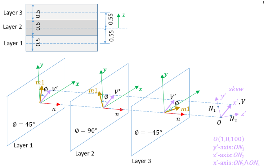
Figure 1.
#RADIOSS STARTER
#---1----|----2----|----3----|----4----|----5----|----6----|----7----|----8----|----9----|---10----|
#-  1. LOCAL_UNIT_SYSTEM:
#---1----|----2----|----3----|----4----|----5----|----6----|----7----|----8----|----9----|---10----|
/UNIT/2
unit for prop
#              MUNIT               LUNIT               TUNIT
                  kg                  mm                  ms
#---1----|----2----|----3----|----4----|----5----|----6----|----7----|----8----|----9----|---10----|
/SKEW/FIX/1
New SKEW 1
#                 OX                  OY                  OZ
                 1.0                   0               100.0
#                 X1                  Y1                  Z1
                   0                   0                   1
#                 X2                  Y2                  Z2
                   0                  -1                   0
#---1----|----2----|----3----|----4----|----5----|----6----|----7----|----8----|----9----|---10----|
#-  2. GEOMETRICAL SETS:
#---1----|----2----|----3----|----4----|----5----|----6----|----7----|----8----|----9----|---10----|
/PROP/SH_SANDW/2/2
SH_SANDW example
#   Ishell    Ismstr     Ish3n     Idril                             Pthick_fail
        12         0         0         0                                       0
#                 hm                  hf                  hr                  dm                  dn
                   0                   0                   0                  .1                  .1
#        N   Istrain               Thick              Ashear              Ithick     Iplas
         3         0                 1.6                   0                   1         1
#                 Vx                  Vy                  Vz   Skew_ID     Iorth      Ipos
                   0                   0                   0         1         0         0
#                Phi                   t                   Z    mat_ID                     F_weighti
                  45                  .5                   0         1                             0
                  90                  .6                   0         2                             0
                 -45                  .5                   0         1                             0
#---1----|----2----|----3----|----4----|----5----|----6----|----7----|----8----|----9----|---10----|
#enddata
#---1----|----2----|----3----|----4----|----5----|----6----|----7----|----8----|----9----|---10----|
Comments
-
Ishell, Ish3n – 4-node and 3-node
shell formulation flag
- Ishell=1,2,3,4 (Q4): original 4 nodes Radioss shell with hourglass perturbation stabilization.
- Ishell=24 (QEPH): formulation with hourglass physical stabilization for general use (istotropic + LAW25 shells only).
- Ishell=12 (QBAT): modified BATOZ Q4γ24 shell with four Gauss integration points and reduced integration for in-plane shear. No hourglass control is needed for this shell.
- Ish3n=30 (DKT18): BATOZ DKT18 thin shell with three Hammer integration points.
- Ismstr- Small strain
formulation
- Small strain formulation is activated from time t = 0, if Ismstr =1 or 3. It may be used for a faster preliminary analysis, but the accuracy of results is not ensured. Any shell for which can be switched to a small strain formulation by Radioss Engine option /DT/SHELL/CST, except if Ismstr =4.
- If Ismstr =1 or 3, the strains and stresses which are given in material laws are engineering strains and stresses; otherwise they are true strains and stresses.
- hm, hf, and hr - Hourglass coefficients
- hm, hf, and hr are only used for Q4 shells. They must have a value between 0 and 0.05.
- For Ishell=3, default values of hm and hr are 0.1 with larger values possible.
- dn - Shell
numerical damping coefficient
- dn is only used for Ishell =
12 and 24.
- for Ishell = 24, dn is used for hourglass stress calculation
- for Ishell= 12 (QBAT), dn is used for all stress terms, except transverse shear
- for Ish3n=30 (DKT18), dn is only used for membrane
- dn is only used for Ishell =
12 and 24.
- Ithick- Shell resultant
stresses calculation flag
- If Ithick=1, the small strain option is automatically deactivated in the corresponding type of element.
- Iplas- Shell plane stress
plasticity flag
- It is recommended to use Iplas =1, if Ithick =1.
- Iplas=1 is available for Material Law 27.
- If Iplas=1, the small strain option is automatically deactivated in the corresponding type of element.
- Output for
post-processing
- Flag Istrain is automatically set to 1 for Material Law 25 and /MAT/LAW27 (PLAS_BRIT).
- Idril - Drilling degree of
freedom stiffness flag
- Drilling DOF stiffness is recommended for implicit solutions especially for Riks method and bending dominated problems.
- Idril is available for QEPH, QBAT (Ishell =12, 24), and standard triangle (C0) shell elements (Ish3n = 1, 2).
- Orthotropy in local
coordinate system.Two different ways to define the orthotropy with this property
- Skew_ID=0:
- Orthotropic direction defined with global vector (components defined in Line 6) and angle (angle in degree) for each layer.
- Skew_ID≠0
- Orthotropic direction defined with skew (X-axis in skew replaces the global vector ) and angle (angle in degree) for each layer.
For both ways (with vector or with skew), Projection of vector (or x-axis of skew)on shell element plane becomes the vector . Then for each layer, the orthotropic direction (direction 1) is vector turn degrees (turns positive direction coding to shell normal ).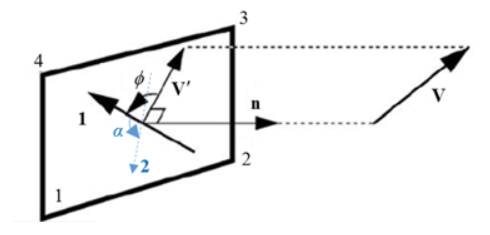
Figure 2.In case of reference metrics, the orientation for directions of anisotropy must be defined with the reference geometry, not the initial one.
- Ipos – Layer position
- Ipos = 0: layer
positions are calculated automatically with "Thick". If
- A warning message is displayed.
- And individual layer thickness will be adjusted to new layer
thickness
with:
(1) Here "Thick" and are the shell thickness and layer thickness which specified in input.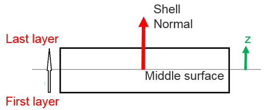
Figure 3.
- Ipos = 1: all layer
positions in the element thickness are user-defined (with
and
).
- “Thick” is not checked, as it does not need to be equal to the sum of layer thickness.
- Multiple layers are allowed to have the same space position.
For more details, refer to “Layer thickness and layer position calculation” in the Property and Elements FAQs.
- Ipos = 0: layer
positions are calculated automatically with "Thick".
- Mat_IDi- Material
for each layer
- Each layer as well as the corresponding part must use the same material law type. But may have different material properties, hence material IDs. Radioss checks for this condition and errors out if it is not met.
- Global material properties (membrane stiffness, bending stiffness, mass, and inertia) are calculated based on the material properties and layer (thicknesses …). They are used for stability, mass and interface stiffness.
- A material is still required at part definition level, but is only used for pre- and post- (visualization “by material”) and its physical characteristics are ignored.
- The previous formulation where stiffness and mass were calculated from the material associated to the part is still used if the version number of the input file is V13 or earlier.
- P_thickfail parameter is not compatible with failure defined within the material law itself, such as plastic failure strain in LAW36.
- Element suppression
rules used with /FAIL models:
- Each single layer is turned OFF when all in-plane Gauss integration points in the layer are deleted.
- The whole shell element is deleted when the following criterion is
met:
(2) with(3) Where, Thicki is relative thickness of failed layer i
- When Ifail_sh parameters are defined locally in failure models associated to each layer material, the P_thickfail value is used by default and local parameter settings are ignored. Local failure model settings are only used when P_thickfail is not defined in the property which allows for backward compatibility with old models.