/FRIC_ORIENT
Block Format Keyword Define specific directions for orthotropic contact friction for the main surface for contact interfaces TYPE7, TYPE19, TYPE24, and TYPE25.
These orientations are used when an orthotropic friction model is defined in /FRICTION Idir=1. Only shell elements are supported.
Format
| (1) | (2) | (3) | (4) | (5) | (6) | (7) | (8) | (9) | (10) |
|---|---|---|---|---|---|---|---|---|---|
| /FRIC_ORIENT/fric_ID | |||||||||
| friction_orientation_title | |||||||||
| (1) | (2) | (3) | (4) | (5) | (6) | (7) | (8) | (9) | (10) |
|---|---|---|---|---|---|---|---|---|---|
| /FRIC_ORIENT/fricorient_ID | |||||||||
| friction_orientation_title | |||||||||
| grpart_ID | part_ID | ||||||||
| VX | VY | VZ | Skew_ID | Iorth | |||||
Definitions
| Field | Contents | SI Unit Example |
|---|---|---|
| fric_ID | Friction
identifier (Integer, maximum 10 digits) |
|
| friction_orientation_title | Friction model
title (Character, maximum 100 characters) |
|
| grpart_ID | Part group identifier
/GRPART. (Integer) |
|
| part_ID | Part
identifier. Ignored if, grpart_ID is defined. (Integer) |
|
| VX | X component for
reference vector. Default = 1.0 (Real) |
|
| VY | Y component for
reference vector. Default = 1.0 (Real) |
|
| VZ | Z component for
reference vector. Default = 1.0 (Real) |
|
| Skew_ID | Skew identifier for
reference vector. 2
If the local skew is defined, its X-axis replaces the global vector, . VX, VY and VZ coordinates are ignored. Default = 0 (Integer) |
|
| Angle. 2 (Real) |
||
| Iorth | Orthotopic system
formulation flag for reference vector.
(Integer) |
Example
#RADIOSS STARTER
#---1----|----2----|----3----|----4----|----5----|----6----|----7----|----8----|----9----|---10----|
/FRICTION/999
test no 1
#    Ifric    Ifiltr               Xfreq     Iform
         0         0                   0         2
# default friction for rest parts which not specifically defined below
#                 C1                  C2                  C3                  C4                  C5
                   0                   0                   0                   0                   0
#                 C6                Fric                VisF
                   0                  .2                   0
#---1----|----2----|----3----|----4----|----5----|----6----|----7----|----8----|----9----|---10----|
#friction between part group ID 111 and ID 222
#GRpartID1 GRpartID2  PartID_1  PartID_2                Idir
       111       222         0         0	               0
#                 C1                  C2                  C3                  C4                  C5
                   0                   0                   0                   0                   0
#                 C6                Fric                VisF
                   0                  .1                   0
#---1----|----2----|----3----|----4----|----5----|----6----|----7----|----8----|----9----|---10----|
#friction between part ID 1 and ID 3
#GRpartID1 GRpartID2  PartID_1  PartID_2                Idir
         0         0         1         3	               0
#                 C1                  C2                  C3                  C4                  C5
                   0                   0                   0                   0                   0
#                 C6                Fric                VisF
                   0                  .2                   0
#---1----|----2----|----3----|----4----|----5----|----6----|----7----|----8----|----9----|---10----|
#friction between part ID 1 and ID 4; orthotropic direction considered
#GRpartID1 GRpartID2  PartID_1  PartID_2                Idir
         0         0         1         4                   1
#                 C1                  C2                  C3                  C4                  C5
                   0                   0                   0                   0                   0
#                 C6                Fric                VisF
                   0                  .4                   0
#                 C1                  C2                  C3                  C4                  C5
                   0                   0                   0                   0                   0
#                 C6                Fric                VisF
                   0                  .2                   0
#---1----|----2----|----3----|----4----|----5----|----6----|----7----|----8----|----9----|---10----|
#friction between part ID 1 and ID 5
#GRpartID1 GRpartID2  PartID_1  PartID_2                Idir
         0         0         1         5	               0
#                 C1                  C2                  C3                  C4                  C5
                   0                   0                   0                   0                   0
#                 C6                Fric                VisF
                   0                  .3                   0
#---1----|----2----|----3----|----4----|----5----|----6----|----7----|----8----|----9----|---10----|
#---1----|----2----|----3----|----4----|----5----|----6----|----7----|----8----|----9----|---10----|
/INTER/TYPE7/2
New INTER 2
#  Slav_id   Mast_id      Istf      Ithe      Igap                Ibag      Idel     Icurv      Iadm
         9        10         4         0         2                   0         1         0         0
#          Fscalegap             Gap_max             Fpenmax
                   0                   0                 0.8
#              Stmin               Stmax          %mesh_size               dtmin  Irem_gap   Irem_i2
                   1                   0                   0                   0         0         0
#              Stfac                Fric              Gapmin              Tstart               Tstop
                   0                 .35                 2.1                   0                   0
#      IBC                        Inacti                VisS                VisF              Bumult
       000                             6                   0                   0                   0
#    Ifric    Ifiltr               Xfreq     Iform   sens_ID   fct_IDf             AscaleF   fric_ID
         0         0                   0         2         0         0                   0         0
/GRNOD/PART/9
INTER_group_9_of_SURF
         4         5
/SURF/PART/10
INTER_group_10_of_PART
         1
#---1----|----2----|----3----|----4----|----5----|----6----|----7----|----8----|----9----|---10----|
#---1----|----2----|----3----|----4----|----5----|----6----|----7----|----8----|----9----|---10----|
/FRIC_ORIENT/1
define orientation of part ID 1
# GRpartID    PartID
                   1
#                 Vx                  Vy                  Vz   skew_ID                 Phi     Iorth
                   1                   0                   1                            45
#---1----|----2----|----3----|----4----|----5----|----6----|----7----|----8----|----9----|---10----|| Parts | Idir | Friction Coefficient | |
|---|---|---|---|
| All parts not listed | - | 0.2 | |
| /GRPART/111 - /GRPART/222 | 0: Isotropic | 0.1 | |
| part_ID1 - part_ID3 | 0: Isotropic | 0.2 | |
| part_ID1 - part_ID4 | 1: Orthotropic | Dir1 = 0.4 | Dir2 = 0.2 |
| part_ID1 - part_ID5 | 0: Isotropic | 0.3 | |
In this example, the orthotripoc direction for friction between parts 1 and 4 is defined by the vector and angle in /FRIC_ORIENT/1.
Comments
- These friction directions replace the orthotropic directions defined in the property for defined parts.
- Orthotropy in local
coordinate system via two different ways:
- Skew_ID =0: Orthotropic direction defined with global vector (components defined in Line 4) and angle (angle in degree).
- Skew_ID ≠0: Orthotropic direction defined with skew (X-axis in skew replaces the global vector ) and angle (angle in degree).
For both ways (with vector or with skew), the projection of vector (or x-axis of skew) on shell element plane becomes the vector . Then the orthotropic direction (direction 1) is vector turned degrees where the positive direction is based on the shell normal .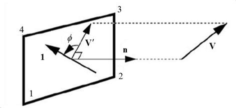
Figure 1.