/INTER/TYPE24
Block Format Keyword TYPE24 is a general nodes-to-surface contact interface using the penalty method.
Penalty stiffness is constant and therefore, the time step is not affected (for standard penalty stiffness). Solid elements are given a zero gap. Three types of inputs contacts can be defined: single surface, surface to surface, or nodes to surface. This contact interface can replace interface TYPE3, TYPE5, or TYPE7. For implicit solution, this interface TYPE24 is only available with SMP.
Format
| (1) | (2) | (3) | (4) | (5) | (6) | (7) | (8) | (9) | (10) |
|---|---|---|---|---|---|---|---|---|---|
| /INTER/TYPE24/inter_ID/unit_ID | |||||||||
| inter_title | |||||||||
| surf_ID1 | surf_ID2 | Istf | Irem_i2 | Idel | |||||
| grnd_IDs | Iedge | Edge_angle | Gap_max_s | Gap_max_m | |||||
| Stmin | Stmax | Igap0 | Ipen0 | Ipen_max | |||||
| (1) | (2) | (3) | (4) | (5) | (6) | (7) | (8) | (9) | (10) |
|---|---|---|---|---|---|---|---|---|---|
| Stfac | Fric | Tstart | Tstop | ||||||
| IBC | Inacti | VISs | |||||||
| Ifric | Ifiltr | Xfreq | sens_ID | fric_ID | |||||
| (1) | (2) | (3) | (4) | (5) | (6) | (7) | (8) | (9) | (10) |
|---|---|---|---|---|---|---|---|---|---|
| C1 | C2 | C3 | C4 | C5 | |||||
| (1) | (2) | (3) | (4) | (5) | (6) | (7) | (8) | (9) | (10) |
|---|---|---|---|---|---|---|---|---|---|
| C6 | |||||||||
Definitions
| Field | Contents | SI Unit Example |
|---|---|---|
| inter_ID | Interface
identifier. (Integer, maximum 10 digits) |
|
| unit_ID | Unit Identifier. (Integer, maximum 10 digits) |
|
| inter_title | Interface
title. (Character, maximum 100 characters) |
|
| surf_ID1 | First surface identifier.
1
(Integer) |
|
| surf_ID2 | Second surface
identifier. (Integer) |
|
| Istf | Interface stiffness
definition flag. 2
3
(Integer) |
|
| Irem_i2 | Deactivating flag for the
secondary node, if the same contact pair (node/segment) has been
defined in interface TYPE2.
|
|
| Idel | Node and segment deletion
flag.
Note: Using Idel results in
higher CPU cost.
|
|
| grnd_IDs | Nodes group
identifier. 1
If defined, node group will be added as secondary nodes. (Integer) |
|
| Iedge | Edge to edge contact flag.
(Integer) |
|
| Edge_angle | Edge angle. Only used if Iedge =1. Sharp edges are included in edge contact if the angle between two segments which share the same edge is smaller than Edge_angle value. 9 Default = 135° (Real) |
|
| Gap_max_s | Secondary maximum gaps.
4 Default = 1030 (Real) |
|
| Gap_max_m | Main maximum gaps. 4
Default = 1030 (Real) |
|
| Stmin | Minimum stiffness (used
only when Istf >
1 and Istf < 7). 2
(Real) |
|
| Stmax | Maximum stiffness (used
only when Istf > 1
and Istf < 7). 2
Default = 1030 (Real) |
|
| Igap0 | Gap modification flag for
secondary shell nodes on the free edges.
(Integer) |
|
| Ipen0 | Initial penetration
detection flag. 8
(Integer) |
|
| Ipen_max | Maximum initial
penetration. 7
Default = 0 (Real) |
|
| Stfac | Interface stiffness scale
factor. 2
Default = 1.0 (Real) |
|
| Fric | Coulomb friction. 5
(Real) |
|
| Tstart | Start time. 9
(Real) |
|
| Tstop | Temporary deactivation
time. 9 Default = 1030 (Real) |
|
| IBC | Deactivation flag of
boundary conditions at impact. (Boolean) |
|
| Inacti | Initial penetration flag.
7
(Integer) |
|
| VISs | Critical damping
coefficient on interface stiffness. Default = 0.05 (Real) |
|
| Ifric | Friction formulation flag.
5 Only used if
fric_ID is not defined.
(Integer) |
|
| Ifiltr | Friction filtering flag.
6
(Integer) |
|
| Xfreq | Filtering coefficient.
6
Default = 1.0 (Real) |
|
| sens_ID | Sensor identifier to
activate/deactivate the interface. 9 (Integer) |
|
| fric_ID | Friction identifier for
friction definition for selected pairs of parts.
(Integer) |
|
| C1 | Friction law coefficient.
5 (Real) |
|
| C2 | Friction law
coefficient. (Real) |
|
| C3 | Friction law
coefficient. (Real) |
|
| C4 | Friction law
coefficient. (Real) |
|
| C5 | Friction law
coefficient. (Real) |
|
| C6 | Friction law
coefficient. (Real) |
Flags for Deactivation of Boundary Conditions: IBC
| (1)-1 | (1)-2 | (1)-3 | (1)-4 | (1)-5 | (1)-6 | (1)-7 | (1)-8 |
|---|---|---|---|---|---|---|---|
| IBCX | IBCY | IBCZ |
Definitions
| Field | Contents | SI Unit Example |
|---|---|---|
| IBCX | Deactivation flag of X
boundary condition at impact.
(Boolean) |
|
| IBCY | Deactivation flag of Y
boundary condition at impact.
(Boolean) |
|
| IBCZ | Deactivation flag of Z
boundary condition at impact.
(Boolean) |
Comments
- Contact main/secondary pairs
can be defined in three ways:
- Single self-impacting surface only: surf_ID1 > 0, and surf_ID2 = 0
- Symmetric surface to surface: surf_ID1 > 0, and surf_ID2 > 0
- Nodes to surface: grnd_IDs > 0, surf_ID1 = 0, and surf_ID2 > 0
grnd_IDs > 0 is used to define node to surface contact type, but it may also be used in other contact types. In that case, the node group will be added simply as supplementary secondary nodes, which is useful when you want to add spring element nodes, main node of rigid body, etc. into the contact (as secondary nodes).
If the surface is defined with shells, two contact segments (shifted by half thickness (t)) with opposite normal directions will be generated: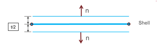
Figure 1.In case of SPMD, each main segment defined by surf_IDi (i=1, 2) must be associated to an element (possibly to a void element).
The surface definition /SURF/PART/ALL is not available with TYPE24.
- Contact stiffness,
K is defined as:
(1) Where, depends on Istf- If Istf = 1000, (Default stiffness)
- Istf = 2,
- Istf = 3,
- Istf = 4,
- Istf = 5,
- Istf = 6,
,
Soft stiffness. This option is only available with implicit solution.
For each contact, to make nonlinear iteration convergence easier, smaller initial stiffness is used; for the function of the reaction of the contacting parts (with increasing penetration or rebound), the stiffness will be adjusted, but is always smaller than the input stiffness.
- Istf = 12, Nitsche method with
- Istf = 13, Nitsche method with
- Istf = 14, Nitsche method with
: main segment stiffness
- , when the main segment lies on a shell
- , when main segment is shared by shell and solid
- , when main segment lies on a solid.
: Secondary node stiffness is an equivalent nodal stiffness considered for interface TYPE24, and computed as:- , when node is connected to a shell element,
- , when node is connected to solid element.
Where,- Segment area
- Volume of the solid
- Bulk modulus
- Thickness of the shell
The Stfac value can be larger than 1.0. There is no limitation value to the stiffness factor (a value larger than 1.0 can reduce the initial time step).
When using /PROP/VOID and /MAT/VOID, material properties and thickness for the VOID material must be entered; otherwise, the contact stiffness of the void elements will be zero. This is especially important if VOID shell elements share elements with solid elements as the stiffness of the shell elements is used in the contact calculation.
If Implicit Analysis is to be considered (defined by /IMPLICIT), the default value is Istf= 4; Istf = 6 is recommended for flexible or bending dominated structures.
- The Nitsche method 1 is a contact algorithm used to resolve contact equations. This method can be used in place of the traditional penalty contact method. Nitsche method is better at preventing contact penetrations especially for cases of contact between components with different material stiffness such as contact between rubber and metal. For these cases, it is difficult to select a penalty stiffness because using the minimum stiffness may lead to large penetrations and using the maximum contact stiffness may result in highly deformed elements and a decreasing time step. The Nitsche method can improve modeling such problems because the contact forces are computed using the contact stiffness, penetrations, and the element's stresses. The Nitsche method is available only for single surface or surface to surface contact between solids and not edge to edge contact.
- The gap is computed
automatically (similar to the variable gap, Igap = 1 of TYPE7)
for each impact as:
(2) While,-
: main element gap:
, with t is the thickness of the main element for shell elements
, for brick elements
-
: secondary node gap:
, if the secondary node is not connected to any element or is only connected to brick or spring elements.
, if the secondary node is connected to a shell element, with being the largest thickness of the shell elements connected to the secondary node.
, if the secondary node is connected to truss or beam elements, with being the cross section of the 1D element.
If the secondary node is connected to multiple shells and/or beams or trusses, the largest computed secondary gap is used.
and are limited separately by Gap_max_m and Gap_max_s before the gap is computed.
Limitation concerning Igap0=1:
Gap modification flag for secondary shell nodes on the free edges has no effect if the secondary node is defined through the optional node group (grnd_IDs).
-
: main element gap:
- If fric_ID is defined, the contact friction is defined in /FRICTION
and the friction inputs (Ifric, C1, etc.) in this input card are not used.The friction forces are:
(3) While an adhesion force is computed as:
with
Where, is the Coulomb friction coefficient and is defined as:- For flag Ifric by default:
with (Coulomb friction)
- For flag Ifric > 1, new friction
models are introduced. In this case, the friction coefficient is set
by a function:Where,
- Pressure of the normal force on the main segment
- Tangential velocity of the secondary node relative to the main segment
Currently, the coefficients C1 through C6 are used to define a variable friction coefficient for new friction formulations.
The following formulations are available:- Ifric = 1
(Generalized Viscous Friction law):
(4) - Ifric = 2
(Modified Darmstad law):
(5) - Ifric = 3
(Renard law):
if
if
if
Where,- First critical velocity must be different to 0 ( ).
- First critical velocity must be less than the second critical velocity .
- The static friction coefficient and the dynamic friction coefficient , must be less than the maximum friction ( and ).
- The minimum friction coefficient must be less than the static friction coefficient and the dynamic friction coefficient ( and ).
Table 1. Units for Friction Formulations Ifric Fric C1 C2 C3 C4 C5 C6 1 2 3
- For flag Ifric by default:
- Friction filteringIf Ifiltr = 1, 2 or 3, the tangential forces are smoothed using a filter:
(6) Where, α coefficient is calculated from:- If Ifiltr = 1: α = Xfreq, simple numerical filter
- If Ifiltr = 2: , standard -3dB filter, with , and = filtering period
- If Ifiltr = 3: , standard -3dB filter, with Xfreq = cutting frequency
The filtering coefficient Xfreq should have a value between 0 and 1.
- Inacti and Ipen_max,
initial penetration treatment:
- Inacti = 1000:
The initial penetrations are ignored: no contact force is applied, but
the nodes are not deactivated from the contact; if the node goes out of
the contact and later gets back into contact, contact forces are then
applied.
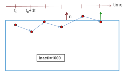
Figure 2. - Inacti = -1:
Initial forces are applied on all penetrating nodes. High initial
penetrations should be avoided, as they might generate high contact
forces and lead to high energy error at the beginning of the
computation.
The contact forces caused by the initial penetration are increased from zero at t=0.0 to full contact force at 10,000 cycles. This slow increase of the contact force allows press fit situations in models to be simulated.
- Inacti = 5: The main segment is shifted by the initial penetration value ( ); therefore, at time zero no initial forces are applied.
The main segment position is restored only in case of rebound larger than .
In the opposite case, when secondary node continues to penetrate, the penetration is computed as:(7) 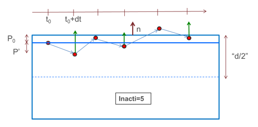
Figure 3.- Intersections and large initial penetration (Inacti= -1 and
5):
Shells and thick shells: initial intersections should be avoided, as they will lead to wrong direction of contact force and possible secondary nodes anchorage.
Solids: by default, the distance which is considered for searching the initial penetration is compute as:(8) While for each main segment,- Volume of the connected solid element
- Segment area
- = 1 to 4 are the lengths of the edges of the segment.
- Number of main segments
- An estimation of the depth of the solid element connected to the segment (limited to the size of the segment)
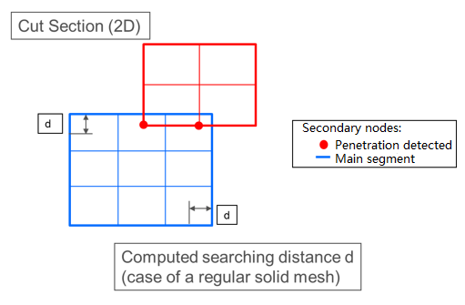
Figure 4.
Maximum initial penetration Ipen_max:- If a non-zero value is input for Ipen_max, this default value is omitted and initial penetrations will be searched within Ipen_max.
- Large value of the searching distance might lead to poor performance of Radioss Starter and/or memory allocation failure. Therefore, it is advised not to set a too large value for Ipen_max.
- Nevertheless, Ipen_max may be used to catch
penetrations larger than the computed (default) searching distance,
as shown in Figure 5:
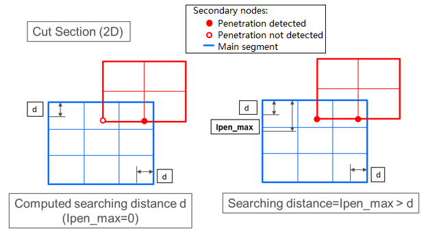
Figure 5.
- Inacti = 1000:
The initial penetrations are ignored: no contact force is applied, but
the nodes are not deactivated from the contact; if the node goes out of
the contact and later gets back into contact, contact forces are then
applied.
- Ipen0, Initial
penetration detection flag:
- By default, the detection of the penetrations for self-impacts for each part (shell and solid elements only) are always excluded (even if surf_ID1 is defined in isolation and Inacti =-1 is set).
- Ipen0 = 1 initial penetrations are taken into account for self-impact for each part and initial forces are set, but in some complex situations, incorrect initial penetrations might be calculated.
- When sens_ID is defined for activation/deactivation of the interface, Tstart and Tstop are not taken into account.
- When edge to edge contact is
activated using
=1, the edge to edge contact is
symmetric and the edges used in contact are automatically generated from the
defined single surface (surf_ID1) or surface to surface contact
(surf_ID1 and surf_ID2):
- For solids and shells
The edges are considered anywhere the angle between two external segments which share the same edge is smaller than Edge_angle value (by default 135°).
- For shellsThe edges are considered at the perimeter border of the shell parts.
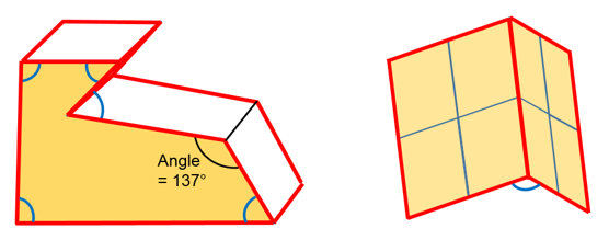
Figure 6.
- For solids and shells
- For output forces:
When the contact type is asymmetric surface to surface, the output normal contact forces in Time History are calculated correctly, if the two surfaces are well separated.
- For implicit solution:
- Interface TYPE24 is only available with SMP
- The default for Istf will be set to 4 (Istf=6 can be used, recommended for flexible or bending dominated structures)
- The default for Inacti will be set to -1