/INTER/TYPE21
Block Format Keyword Specific interface between a non-deformable main surface and a secondary surface designed for stamping. All nodes of the main surface must belong to the rigid body.
Description
- A node cannot be a secondary and a main node at the same time.
- The normals to the main segments must be oriented toward the secondary surface.
- For each secondary node, a single impact will be retained, in a way which ensures continuity of the normal force and the tangent force when this impact slides from one segment to a neighboring one.
- Gap may vary according to the variation of shells and 3-node shells thickness, on the secondary side.
- Fast search algorithm.
- High speed-up with SPMD version.
Format
| (1) | (2) | (3) | (4) | (5) | (6) | (7) | (8) | (9) | (10) |
|---|---|---|---|---|---|---|---|---|---|
| /INTER/TYPE21/inter_ID/unit_ID | |||||||||
| inter_title | |||||||||
| surf_IDs | surf_IDm | Istf | Ithe | Igap | Idel | Invn | Iadm | ||
| Fscalegap | Gapmax | DEPTH | Pmax | ITlim | |||||
| Stmin | Stmax | Pskid | |||||||
| Stfac | Fric | Gapmin | Tstart | Tstop | |||||
| IBC | Inacti | VISs | Bumult | ||||||
| Ifric | Ifiltr | Xfreq | sens_ID | fct_IDF | AscaleF | ||||
| (1) | (2) | (3) | (4) | (5) | (6) | (7) | (8) | (9) | (10) |
|---|---|---|---|---|---|---|---|---|---|
| C1 | C2 | C3 | C4 | C5 | |||||
| (1) | (2) | (3) | (4) | (5) | (6) | (7) | (8) | (9) | (10) |
|---|---|---|---|---|---|---|---|---|---|
| C6 | |||||||||
| (1) | (2) | (3) | (4) | (5) | (6) | (7) | (8) | (9) | (10) |
|---|---|---|---|---|---|---|---|---|---|
| NRadm | Padm | Angladm | |||||||
| Kthe | fct_IDK | AscaleK | Tint | Ithe_form | |||||
| Frad | Drad | Fheat | Fcond | Dcond | |||||
| IDrby | IDref | Damp | Dampr | ||||||
Definitions
| Field | Contents | SI Unit Example |
|---|---|---|
| inter_ID | Interface
identifier. (Integer, maximum 10 digits) |
|
| unit_ID | Unit Identifier. (Integer, maximum 10 digits) |
|
| inter_title | Interface
title. (Character, maximum 100 characters) |
|
| surf_IDs | Secondary surface
identifier. (Integer) |
|
| surf_IDm | Main surface
identifier. (Integer) |
|
| Istf | Stiffness definition flag.
(Integer) |
|
| Ithe | Heat transfer flag.
(Integer) |
|
| Igap | Gap/element option flag.
2
(Integer) |
|
| Idel | Secondary node deletion flag.
(Integer) |
|
| Invn | Test flag for inverted
main normals. 21
(Integer) |
|
| Iadm | Computing local curvature
flag for adaptive meshing. 3
(Integer) |
|
| Fscalegap | Gap scale
factor. Default = 1.0 (Real) |
|
| Gapmax | Maximum
gap. (Real) |
|
| DEPTH | The drawbead depth. 4
(Real) |
|
| Pmax | Maximum contact pressure,
due to thickening. 5
Default = 1030 (Real) |
|
| ITlim | Activate tangential force
limitations. 5
(Integer) |
|
| Stmin | Minimum
stiffness. (Real) |
|
| Stmax | Maximum
stiffness. Default = 1030 (Real) |
|
| Pskid | Maximum contact pressure
used for defining a limit tangential force for skid line output
(/H3D/NODA/SKID_LINE). Default = 1030 (Real) |
|
| Stfac | Interface stiffness (if
Istf =
1). Default set to 0.0 (Real) |
|
| Stiffness scale factor for
the interface (if Istf =
0). Default set to 1.0 (Real) |
||
| Fric | Coulomb friction (if fct_IDF =
0). Default = 0.0 (Real) |
|
| Coulomb friction scale
factor (if fct_IDF
0). Default = 1.0 (Real) |
||
| Gapmin | Minimum gap for impact
activation. (Real) |
|
| Tstart | Start
time. (Real) |
|
| Tstop | Time for temporary
deactivation. (Real) |
|
| IBC | Deactivation flag of
boundary conditions at impact. (Boolean) |
|
| Inacti | Deactivation flag of
stiffness in case of initial penetrations. 9
(Integer) |
|
| VISs | Critical damping
coefficient on interface stiffness. Default set to 1.0 (Real) |
|
| Bumult | Sorting factor is used to
speed up the sorting algorithm. 10 Default set to 0.20 (Real) |
|
| Ifric | Friction formulation flag.
12
13
(Integer) |
|
| Ifiltr | Friction filtering flag.
15
(Integer) |
|
| Xfreq | Filtering coefficient.
15 (Real) |
|
| sens_ID | Sensor identifier to
activate/deactivate the interface. 20 If an identifier sensor is defined, the activation/deactivation of interface is based on sensor and not on Tstart or Tstop. (Integer) |
|
| fct_IDF | Function identifier for
friction coefficient with temperature. Default = 0 (Integer) |
|
| AscaleF | Abscissa scale factor on
fct_IDF. Default = 1.0 (Real) |
|
| C1 | Friction law coefficient . (Real) |
|
| C2 | Friction law
coefficient. (Real) |
|
| C3 | Friction law
coefficient. (Real) |
|
| C4 | Friction law
coefficient. (Real) |
|
| C5 | Friction law
coefficient. (Real) |
|
| C6 | Friction law
coefficient. (Real) |
|
| NRadm | Number of elements through
a 90° radius (used only if Iadm =2). Default = 3 (Integer) |
|
| Padm | Criteria on the percentage
of penetration. Default = 1.0 (Real) |
|
| Angladm | Angle
criteria. (Real) |
|
| Kthe | Conductive heat exchange
coefficient (if fct_IDK =
0). Default = 0.0 (Real) |
|
| Heat exchange scale factor
(if fct_IDK≠
0). Default = 0.0 (Real) |
||
| fct_IDK | Function identifier for
heat exchange definition with contact pressure. Default = 0 (Integer) |
|
| AscaleK | Abscissa scale factor on
fct_IDK. Default = 1.0 (Real) |
|
| Tint | Interface
temperature. (Real) |
|
| Ithe_form | Heat contact formulation flag.
(Integer) |
|
| Frad | Radiation factor. 17 (Real) |
|
| Drad | Maximum distance for
radiation computation. (Real) |
|
| Fheat | Frictional heating factor.
18 (Real) |
|
| Fcond | Function identifier for
the conductive heat exchange coefficient definition as a function of
distance. 19 Default = 0 (Integer) 22 |
|
| Dcond | Maximum distance for
conductive heat exchange. 23 Default = 0.0 (Real) |
|
| IDrby | Rigid body
identifier. (Integer) |
|
| IDref | Reference interface TYPE21
identifier for damping.
(Integer) |
|
| Damp | Translational critical
damping factor. 19
(Real) |
|
| Dampr | Rotational critical
damping factor. (Real) |
Comments
- In case of SPMD, each main segment defined by surf_IDm must be associated to an element (possibly to a void element).
- Contact gap
- If Igap = 0
(constant gap),
Gap is constant over the secondary surface and along the time, equal to Gapmin. And a default value for Gapmin is computed as , being the average thickness of the secondary shell elements.
In case of constant gap, Gapmax and Fscalegap will not be used.
If contact thickness of the part is not defined in input /PART:
- If Igap = 1,
variable gap over the secondary surface is computed as:
(1) - If Igap = 2,
variable gap over the secondary surface and along the time is computed
at each time, as:
(2) and will vary along the time according to the variation of shells and 3-node shells thickness, on the secondary side.
If contact thickness of the part is defined in input /PART:
- If Igap = 1,
variable gap is computed as:
(3) - If Igap = 2,
variable gap is computed as:
(4) Where,-
: secondary node gap
, with is thickness of the secondary element for shell elements.
for brick elements.
- is the contact thickness of the part.
- is the initial thickness of the secondary node.
If Igap = 1 or 2, the variable gap is always at most equal to Gapmax and default value for Gapmax will be set to 1030 and is always at least equal to Gapmin (but there is no default value for Gapmax).
-
: secondary node gap
- If Igap = 0
(constant gap),
- In case of adaptive meshing:
- Iadm =
1:If the contact occurs in a zone (main side) whose radius of curvature is lower than the element size (secondary side), the element on the secondary side will be divided (if not yet at maximum level).

Figure 1. - Iadm =
2:
If the contact occurs in a zone (main side) whose radius of curvature is lower than NRadm times the element size (secondary side), the element on the secondary side will be divided (if not yet at maximum level).
If the contact occurs in a zone (main side) where the angles between the normals are greater than Angladm, and the percentage of penetration is greater than Padm, the element on the secondary side will be divided (if not yet at maximum level).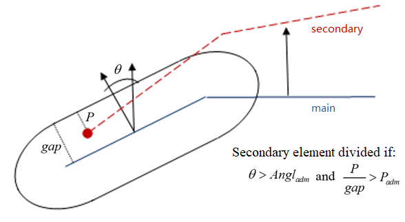
Figure 2.
- Iadm =
1:
- The interface allows secondary
nodes to cross the main surface; if a secondary node gets into the main surface
from a distance greater than DEPTH, no contact force is computed on the node.
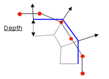
Figure 3.A default value for DEPTH is computed as the maximum of:- Upper value of the gap (at time 0) among all nodes
- Smallest side length of secondary element
If the input value is not equal to 0, DEPTH will be raised up to the upper value of the gap (at time 0) among all nodes.
Too large of a DEPTH will decrease the performances of search algorithms for contact.
- Maximum contact pressure due to
thickening. Pmax is used only
if Igap = 2.
- It can be used for limiting the contact force in case of thickening.
- It can be used for limiting the normal contact force in case of
thickening according to the following equation:
(5) - The tangent contact force is also limited when the flag
ITlim =
0 by the following equation:
(6)
-
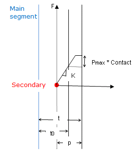
Figure 4. - Stfac can be larger than 1.0.
- Deactivation of the boundary condition is applied to secondary nodes.
- Inacti = 3 may create
initial energy if the node belongs to a spring element.
Inacti = 5 or Inacti = 6, the gap is initially reduced and recovers its computed value as the secondary node depenetrates.
Inacti = 6 is recommended instead of Inacti =5, to avoid high frequency effects into the interface.
Figure 5. - The default value for Bumult is automatically increased to 0.30 for models which have more than 1.5 million nodes and to 0.40 for models with more than 2.5 million of nodes.
- There is no limitation value to the stiffness factor (but a value larger than 1.0 can reduce the initial time step).
- For friction formulation
- If the friction flag Ifric = 0
(default), the old static friction formulation is used:with is Coulomb Friction coefficient.
- If fct_IDF =
0
Fric is Coulomb friction
-
If fct_IDF ≠ 0
Fric becomes a scale factor of Coulomb friction coefficient which depends on the temperature.(7) While, is the interface temperature which is taken as the mean temperature of secondary and main:(8)
- If fct_IDF =
0
- For flag Ifric > 0,
new friction models are introduced. In this case, the friction
coefficient is set by a function.
(9) Where,- Pressure of the normal force on the main segment
- Tangential velocity of the secondary node relative to the main segment
- If the friction flag Ifric = 0
(default), the old static friction formulation is used:
- Currently, the coefficients C1 through C6 are used (if Ifric = 0) and C6 is not used (if Ifric = 1) to define
a variable friction coefficient
for new friction formulations.The following formulations are available:
- Ifric = 1
(Generalized Viscous Friction Law):
(10) - Ifric = 2
(Modified Darmstad Law):
(11) - Ifric = 3
(Renard law):
if
if
if
Where,
- First critical velocity must be different to 0 ( ).
- First critical velocity must be lower than the second critical velocity ( ).
- The static friction coefficient and the dynamic friction coefficient , must be less than the maximum friction ( and ).
- The minimum friction coefficient must be less than the static friction coefficient and the dynamic friction coefficient ( and ).
Table 1. Units for Friction Formulations Ifric Fric C1 C2 C3 C4 C5 C6 1 2 3 - Ifric = 1
(Generalized Viscous Friction Law):
- The formulation for friction is a
stiffness (incremental) formulation, and the friction forces
are:
(12) While and adhesion force is computed as:
with
Where, is the tangential relative velocity of the secondary node with the main segment.
- Friction filtering:If Ifiltr ≠ 0 , the tangential forces are smoothed using a filter:
(13) Where α coefficient is calculated from:- If Ifiltr = 1: , simple numerical filter
- If Ifiltr = 2: , standard -3dB filter, with , and is the filtering period
- If Ifiltr = 3: , standard -3dB filter, with Xfreq is cutting frequency
The filtering coefficient Xfreq should have a value between 0 and 1.
- Heat exchangeBy Ithe= 1 (heat transfer activated) to consider heat exchange and heat friction in contact.
- If Ithe_form =0, then heat exchange is between shell and constant temperature contact Tint.
- If Ithe_form =1, then heat exchange is between all contact pieces.
Tint is used only when Ithe_form= 0. In this case. The temperature of main side assumed to be constant (equal to Tint). If Ithe_form= 1, then Tint is not taken into account. So the nodal temperature of main side will be considered.
If Ithe = 2, Heat transfer is computed using thermal conductance Kthe only for the secondary side. The temperature of the main side is not assumed to be a constant but is calculated from the temperature field defined on each main node. These nodal temperatures can vary over time and space which are defined using /IMPTEMP.
Thermal conduction
Ithe = 1 needs the material of the secondary side to be a thermal material using finite element formulation for heat transfer (/HEAT/MAT).
Thermal conduction is computed when the secondary node falls into gap:(14) Heat exchange coefficient- If fct_IDK = 0, then Kthe is heat exchange coefficient and heat exchange depends only on heat exchange surface.
- If fct_IDK ≠
0, Kthe is a scale factor
and heat exchange depends on contact pressure:
(15) While is the function of fct_IDK.
- Radiation:Radiation is considered in contact if and the distance, , of the secondary node to the main segment is:
(16) While is the maximum distance for radiation computation. The default value for is computed as the maximum of:- Upper value of the Gap (at time 0) among all nodes
- Smallest side length of secondary element
It is recommended not to set the value too high for , which may reduce the performance of Radioss Engine.
A radiant heat transfer conductance is computed as:(17) with(18) Where,- Stefan Boltzman constant
- Emissivity of secondary surface
- Emissivity of main surface
- Heat Friction
- Frictional energy is converted into heat when Ithe > 0 for interface
- Fheat is defined as the fraction of this energy which is converted into heat and transferred to the secondary side.
- The frictional heat QFric
is so defined for a stiffness formulation:
(19)
- Critical damping factors allow
for the reduction of dynamic effects, especially for those tools where a loading
is applied. This can be used to model the hydraulic press system:
A damping force (resp. torque) is applied to the tool:
(resp.)
With resp.
Where,
is a percentage of the critical damping with the tool mass mass (resp. inertia ).
is the total interface stiffness (resp. rotational stiffness ).
(resp. ) is the translational (resp. rotational) velocity of the tool, if IDref is equal to 0; otherwise, it is the relative velocity with respect to tool of interface IDref.
- When sens_ID is defined for activation/deactivation of the interface, Tstart and Tstop are not taken into account.
- If Invn =
1, Radioss will check if main
normal are oriented towards the blank or not. Not well oriented normal may cause
big penetrations and wrong results. If this happens, it is important to stop
computation when this problem is detected. This option used to check if
secondary node is contacting the main segment from the correct side (Figure 6) at the time of first impact.
If not, the computation is stopped with an error message.
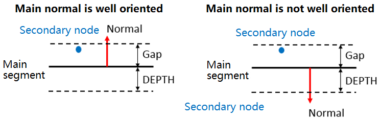
Figure 6.- Main normal is well oriented: First impact is from correct side (penetration is smaller than Gap).
- Main normal is not well oriented: First impact is from wrong side (penetration is almost equal to DEPTH).
This option is only available for shells and must be used with a special care, because the computation can be stopped even if the normals are well oriented when there are large initial penetrations.
- When
Fcond ≠0, the heat transfer coefficient can change as
function of distance d when Gap < d ≤
Dcond.
Abscises and ordinates of this function must be between 0 and 1.
The heat transfer coefficient is computed as:(20) The maximum value of is equal to the value of Kthe when Kthe is constant. Otherwise, in case of Kthe depending on pressure, the maximum is equal to value of Kthe for contact pressure =0.
drops to zero when distance is equal to Dcond.
- When
Fcond≠0, the heat transfer is computed as:
- Conductive heat transfer when d < Gap
- Conductive and radiative heat transfer when Gap < d ≤ Dcond.
- Radiative heat transfer when Dcond < d ≤ Drad
- When
Fcond ≠ 0 and Dcond = 0, then
Dcond=Drad.
When Frad ≠ 0, Fcond ≠ 0, and Drad = 0, then Drad = Dcond.