General Purpose Contact (TYPE7)
- Impacts occur between a main surface and a set of secondary nodes, similar to TYPE5 interface.
- A node can impact on one or more mainr segments.
- A node can impact on either side of a main surface.
- Each secondary node can impact each main segment except if it is connected to this segment.
- A node can belong to a main surface and a set of secondary nodes, as shown in Figure 1.
- A node can impact on the edge and corners of a main segment. None of the previous interfaces allow this.
- Edge to edge contacts between main and secondary segments are not solved by this interface.
Limitations
All limitations encountered with interface TYPE3, TYPE4 and TYPE5 are solved with this interface.
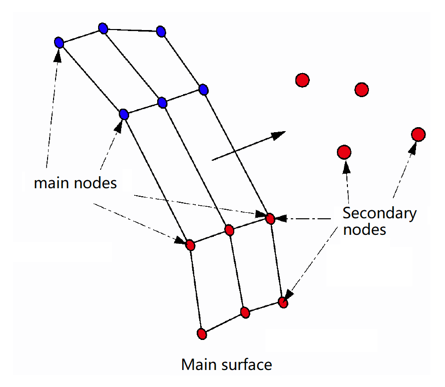
Figure 1. Secondary and Main Node Impact
There are no search limitations with this interface concerning node to surface contacts. All possible contacts are found.
There is no limitation on the use of large and small segments on the same interface. This is recommended to have a good aspect ratio elements or a regular mesh to obtain reasonable results; however, it is not an obligation.
There is no limitation to the size of the spring stiffness factor. The spring stiffness is much greater than interfaces TYPE3 and TYPE5, with the default stiffness factor set to 1.0. This is to avoid node penetrations larger than the gap size, removing problems that were associated with the other interfaces.
Interface Stiffness
When two surfaces contact, a massless stiffness is introduced to reduce the penetration of one surface node to the other surface.
The nature of the stiffness depends on the type of interface and the elements involved.
The introduction of this stiffness may have consequences on the time step, depending on the interface type used.
The interface spring stiffness calculation is not as simple as for TYPE3, TYPE4 and TYPE5. The initial stiffness is calculated using the methods for TYPE3 interfaces. However, after initial penetration, the stiffness is given as a function of the penetration distance and the rate of penetration.
The stiffness is much larger than the other interfaces to accommodate high speed impacts with minimal crossing of surfaces. The consequence of this is that a stable time step is calculated to maintain solution stability.
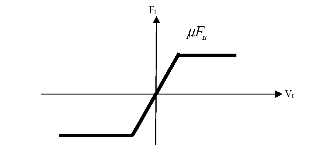
Interface Friction
TYPE7 interface allows sliding between contact surfaces.
Coulomb friction between the surfaces is modelled. The input card requires a friction coefficient. No value (default) defines zero friction between the surfaces.
In TYPE7 interface a critical viscous damping coefficient is defined, allowing viscous damped sliding.
- Tangent displacement
- Initial interface spring stiffness (as in TYPE5)
- Critical damping coefficient on interface stiffness (input)
-
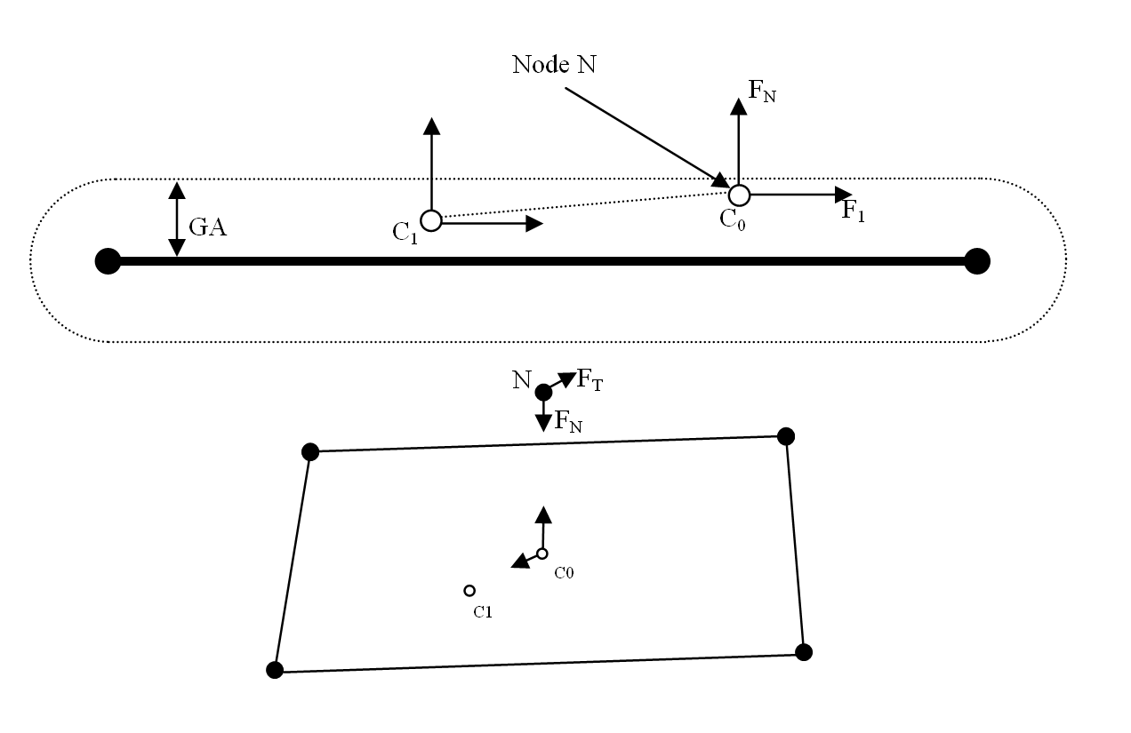
Figure 2. Coulomb Friction - Contact Point at time t
- Contact Point at time
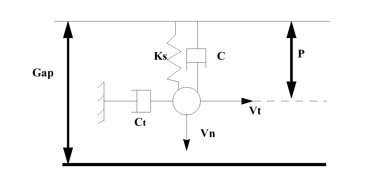
Figure 3. Friction on TYPE7 Interface - Scheme
- Adhesion force
- Tangential velocity calculated from the movement of the node from to in Figure 2.
Interface Gap
TYPE7 interfaces have a gap that determines when contact between two segments occurs.
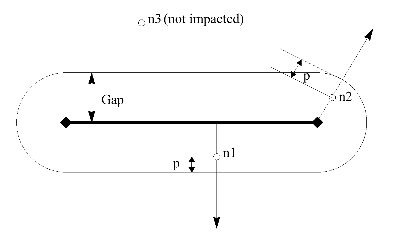
Figure 5. TYPE7 Interface Gap
TYPE7 interface has a gap that covers both edges of the segments, as shown in Figure 5.
Time Step
A time step is calculated to maintain stability when a TYPE7 interface is used.
- Nodal mass
- Nodal stiffness
The time step used for the interface is the smaller of the two. If the interface spring stiffness is too great, the time step can be reduced dramatically. If the two materials involved in the contact are the same, the default interface stiffness factor can be retained. This is the case when modelling sheet metal. However, the stiffness factor may need adjustment if the two materials stiffness' vary too much; for example, steel and foam.
Methods to Increase Time Step
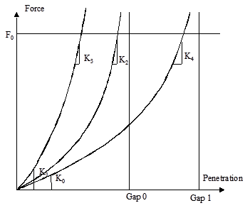
Figure 6. Force - Penetration Curves
Using a larger gap size, curves 1 and 2 keep the same initial stiffness; hence the initial time step remains the same. Since the impact slowing force is applied over a greater distance, the stiffness is not changed as much, but increases.
Increasing the initial interface stiffness, although decreasing the time step initially; will increase the time step if penetration is large.
Detection and Gap Size
A secondary node can be detected near a main segment from all directions, as shown in Figure 7.
The size of the gap can be user defined, but Radioss automatically calculates a default gap size, based on the size of the interface elements. For shell elements, the computed gap is the average thickness. For brick elements it is equal to one tenth of the minimum side length.
Variable Gap
By default the gap is constant on all main segments.
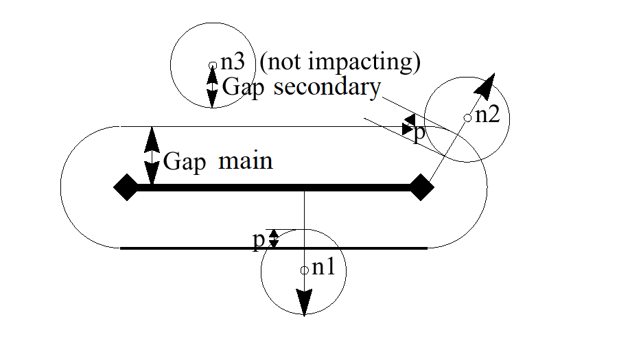
Figure 7. Variable Gap
For shell elements, the main gap is equal to one half of the shell thickness. The secondary gap is equal to one half of the largest thickness of all connected shell elements.
For solid elements, the main gap is zero. If the secondary node is only connected to solid elements, the secondary gap is zero.
For beam or truss elements connected to the secondary node, the secondary gap is one half of the square root of the section area.
If a secondary node is connected to different elements (shell, brick, beam, and truss) the largest gap value is used.
The total gap is the sum of the secondary and main gaps. The total gap cannot be smaller than a minimum gap (user input gap).
Gap Correction
TYPE7 interface is very sensitive to initial penetrations. One method for solving the resulting problems is to use an automatic gap correction (Inacti = 5).
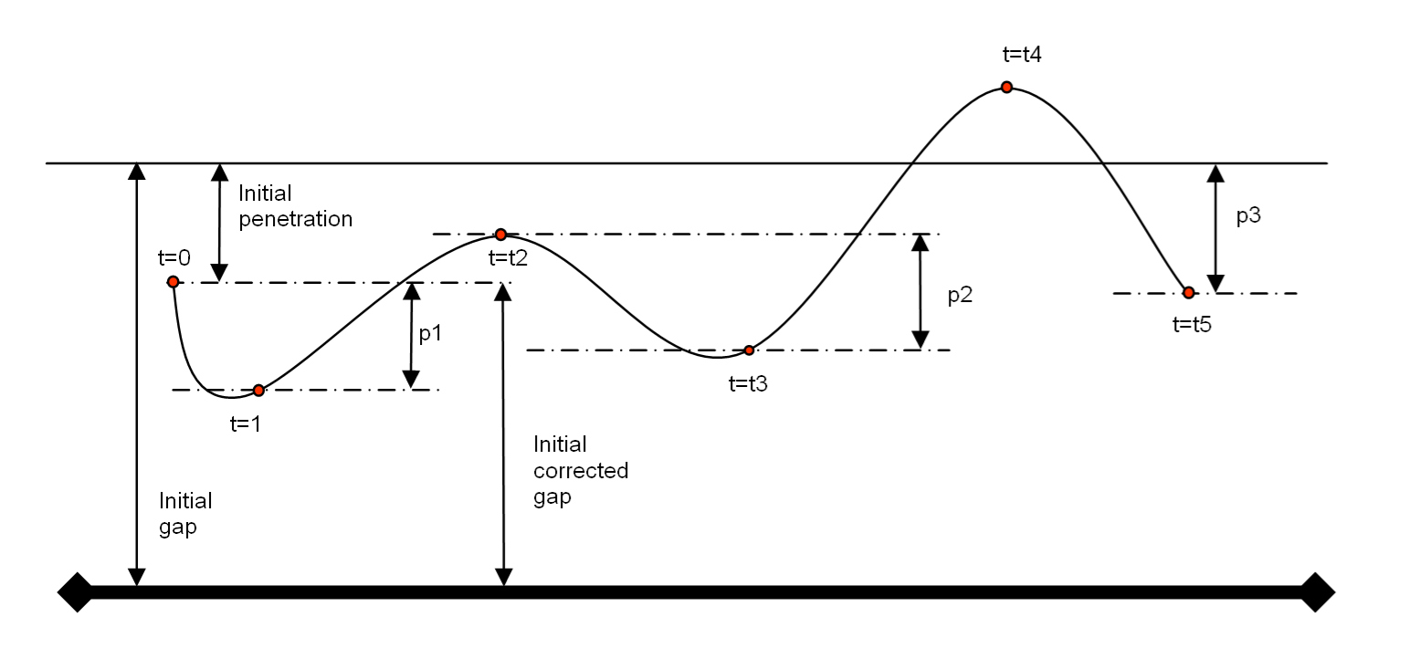
Figure 8. Corrected Gap
Penetration Reaction
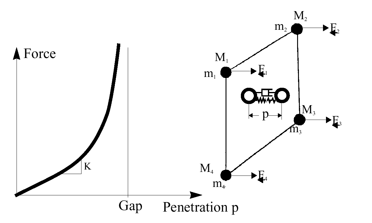
Figure 9. Penetration Reaction Force
The reaction force is not a linear relation like the previous interfaces. There is a viscous damping which acts on the rate of penetration.
- Initial interface spring stiffness (as in TYPE5)
- Critical damping coefficient on interface stiffness (input)
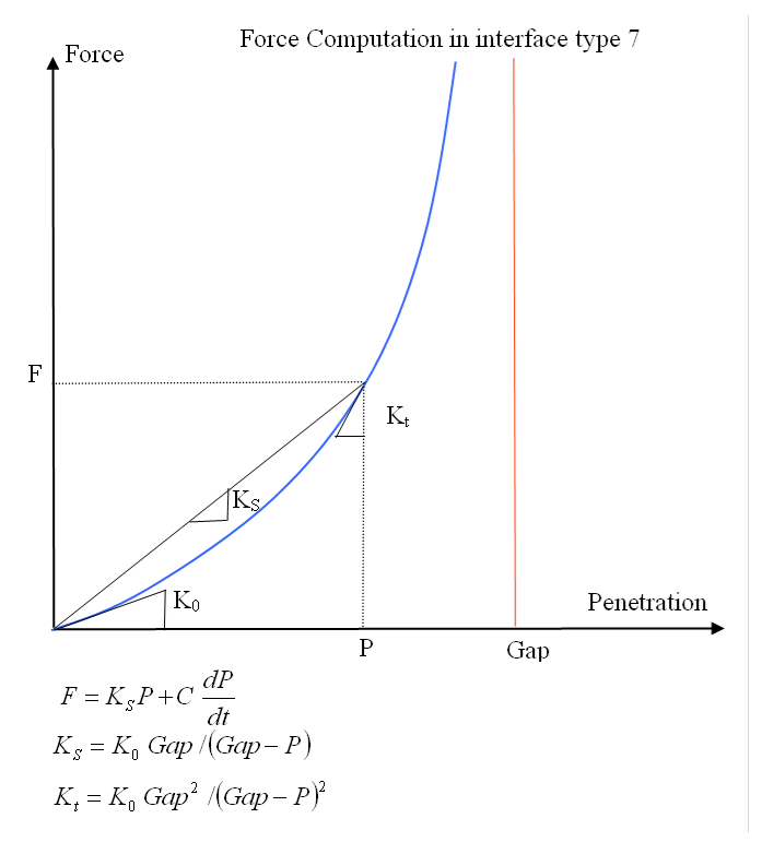
Figure 10. Force - Penetration Graph
A critical viscous damping is required to be defined on the TYPE7 input card for both damping on the spring stiffness and for interface friction damping.
Force Orientation
Due to the gap on a TYPE7 interface extending around the edges of a segment, the reaction forces over a surface will be smooth.
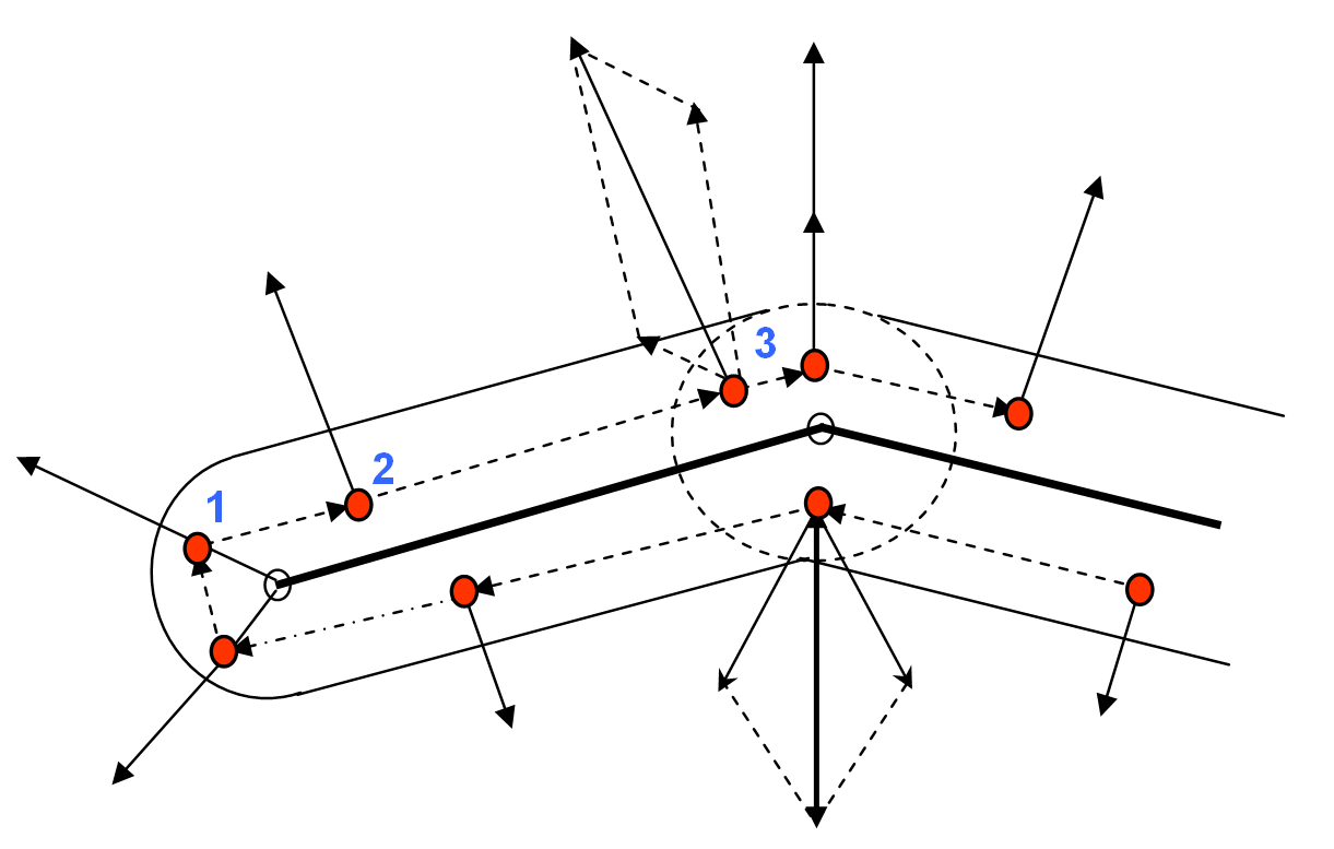
Figure 11. Force Orientation
Position 1 in Figure 11 shows the force acting radially from the edge of the segment. The size of the force depends on the amount of penetration. At position 2 the force is normal to the segment surface. In position 3 two segments intersect and their gaps overlap. The result is that each segment applies a force to the node, normal to the respective segment, this may double the force for the distance of gap overlap.
Interface Hints
Main Problem
- A very small time step
- A large contact force vector in animation
- Initial penetrations of adjacent plates
- Edge impacts: wrong side contacts
- Full collapse of one structural region
- Rigid body impact on another rigid body or on fixed nodes or on very stiff structures
- Impact between heavy stiff structures
- High impact speed
- Small gap
With
- Interface stiffness
- Contact gap
- Penetration
When node to element mid-plane distance is smaller then 10-10 gap, the node is deactivated.
- elastic contact energy CE = 23 kg
Drastic time step dropping is mostly due to cases where node is forced into the gap region.
Remedies to the Main Problem
- Increase Gap
Increasing the gap is the best remedy, but check that no initial penetrations result from this.
- Increase Stiffness
Increase Stfac dimensionless stiffness factor or provide an appropriate effective global stiffness value (v23 and up).
- /DT/INTER/DEL (Engine option)
Some nodes will be allowed to cross the impacted surface freely before penetration reaches (1-1010 ) gap.
- /DT/INTER/CST (Engine option)
Nodal mass will be modified to maintain time step constant. This option should be avoided when rigid body secondary nodes are secondary of a TYPE7 interface.
The initial penetrations are mostly due to discretization and modelization problems.
They result in high initial forces that should be avoided.
- Modify geometry
New coordinates are proposed in the output file for all initially penetrated nodes. These are the coordinates used in the automatic coordinate change option. However, this might not suffice. Several iterations are sometimes necessary. Radioss will create a file RootD0A containing the modified geometry.
- Reduce gap
When there are only small penetrations with a gap, this should be reduced; otherwise care should be taken as this will reduce potential contact energy.
- Deactivate node stiffness
This solution is the simplest. It will generally not unduly affect your results. For sake of precision, use this option only for initial penetrations remaining after geometrical adjustments.
Edge Contact Problem
A special algorithm is developed for this purpose.
Modelization should eventually be adapted to prevent situations where 2 nodes of an element move to opposite sides of a surface.
For solid to solid contacts, the external closed surfaces may be used.