Rigid Body Contact (TYPE6)
This interface is used to simulate impacts between two rigid bodies.
It works like TYPE3 interface except that the total interface force is a user defined function of the maximum penetration. The input and computational algorithms are the same as for TYPE3 interfaces. This interface is used extensively in vehicle occupant simulations; example, knee bolsters.
Limitations
- Surface 1 must be part of one and only one rigid body.
- Surface 2 must be part of one and only one rigid body.
- The interface stiffness (user defined function) can reduce the time step.
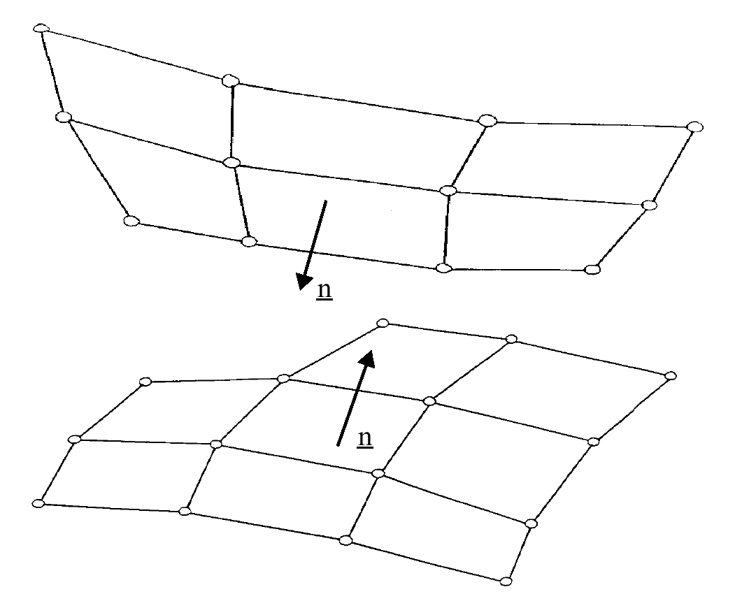
Figure 1. Surfaces 1 and 2 with Facing Normals
Interface Stiffness
When two surfaces contact, a massless stiffness is introduced to reduce the penetration's nodes of the other surface into the surface.
The nature of the stiffness depends on the type of interface and the elements involved.
If a segment is a shell as well as the face of brick element, the shell stiffness is used.
Interface Friction
TYPE6 interface allows sliding between contact surfaces. Coulomb friction between the surfaces is modeled. The input card requires a friction coefficient. No value (default) defines zero friction between the surfaces. The friction computation on a surface is the same as for TYPE3 interface (refer to Contact Processing).
Interface Gap
Refer to Contact Detection for TYPE3 interface.
Time Step Calculation
- min(M rigid body 1, M rigid body 2)
- Tangent of user force function
The function refers to a function number given in input and must be user-defined.
Contact Force
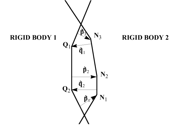
Figure 2. Especially Suited for Rigid Bodies
is the contribution to node of vector distributed on the segment penetrated by node .