Interface Overview
- TYPE1
- Tied contact (boundary) between an ALE part and a Lagrangian part.
- TYPE2
- Tied contact
- TYPE3
- Used to simulate impacts and contacts on shell and solid elements. Surfaces should be simply convex.
- TYPE5
- Used to simulate impacts and contacts between a main surface and a list of secondary nodes. Best suited for beam, truss and spring impacts on a surface.
- TYPE6
- Used to simulate impacts and contacts between two rigid surfaces.
- TYPE7
- A general interface that removes the limitations of TYPE3 and TYPE5.
- TYPE8
- Drawbead contact for stamping applications.
- TYPE9
- ALE Lagrange with void opening and free surface.
- TYPE10
- Tied after impact with or without rebound.
- TYPE11
- Edge to edge or line to line impact.
- TYPE12
- Connects 2 fluid meshes with free, tied or periodic options.
- TYPE14
- Ellipsoidal surfaces to nodes contact.
- TYPE15
- Ellipsoidal surfaces to segments contact.
- TYPE18
- Coupling between a Lagrangian material and an ALE material.
- TYPE19
- General contact interface.
- TYPE20
- Single surface, surface to surface with optional Edge to Edge contact.
- TYPE21
- Specific interface between a non-deformable main surface and a secondary surface designed for stamping.
Each of these interfaces was developed for a specific application field. However, this application field is not the only selection criteria. Some limitations of the different algorithms used in each interface can also determine the choice.
The algorithm limitations concern mainly the search of the impacted segment. This search may be performed directly (TYPE7, TYPE10, and TYPE11 interfaces), or via a search of the nearest node (TYPE3, TYPE5, and TYPE6 interfaces).
Apart from the limitation of the nearest node search, some limitations exist for the choice between the segments connected to the nearest node. These limitations are the same for TYPE3, TYPE5 and TYPE6 interfaces.
TYPE3, TYPE5 and TYPE6 interfaces also have some limitations due to the orientation of the normal segment.
TYPE7 interface was written to emulate TYPE3 and TYPE5 interfaces without algorithm limitations. With this interface, each node can impact one or more segments, on both sides, on the edges or on the corners of the segments. The only limitation to this interface concerns high impact speed and/or small gap. For these situations the interface will continue to work properly, but the time step can decrease dramatically.
TYPE3, TYPE5 and TYPE7 interfaces are compatible with all Radioss kinematic options.
TYPE1 interface is a special option used with solid elements to provide mesh transition. TYPE1 interface is used to connect a Lagrangian and an ALE mesh.
TYPE2 interface is used to connect a fine and a coarse Lagrangian mesh.
All other interface types (TYPE3, TYPE4, TYPE5, TYPE6 and TYPE7) are used to simulate impacts and contacts.
A node may belong to several interfaces.
Surface (Segment) Definition
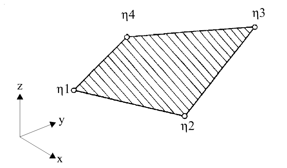
Figure 1. Shell Elements Segment
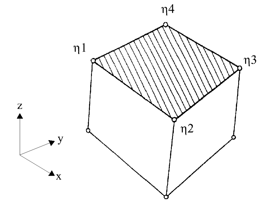
Figure 2. Brick Element Segment
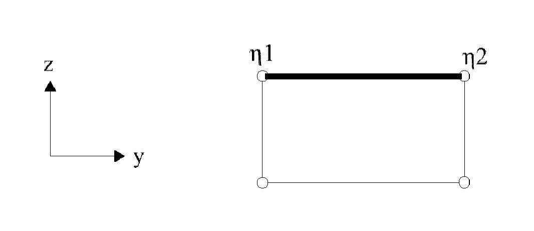
Figure 3. 2D Element Segment