Solid and Shell Element Contact (TYPE3)

The main use of this interface is with shell or solid plates that are initially in contact.

There are no main and secondary surfaces in this interface. Each surface is considered as if it were a secondary.

Limitations

The main limitations of TYPE3 interfaces are:
  • The two surfaces should be simply convex.
  • The surface normals must face each other.
  • A node may not exist on the main and secondary side of an interface simultaneously.
  • Surfaces must consist of either shell or brick elements.

It is recommended that the two surface meshes be regular with a good aspect ratio. The interface gap should be kept small, if not zero.

There are some search problems associated with this interface.


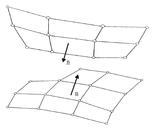
Figure 1. Surfaces 1 and 2 with Facing Normals

Computation Algorithm

The computation and search algorithms used for TYPE3 interface are the same as for TYPE5. However, TYPE3 interface does not have a main surface, so that the algorithms are applied twice, one for each surface.

The surfaces are treated symmetrically, with all nodes allowed to penetrate the opposing surface. The interface spring stiffness applies the opposing penetration reduction force.


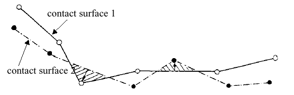
Figure 2. Contact Surfaces Treated Symmetrically

Because the computation algorithm is performed twice, accuracy is improved over a TYPE5 interface. However, the computational cost is increased.

The first pass solution solves the penetration of the nodes on surface 1 with respect to segments on surface 2. The second pass solves surface 2 nodes with respect to surface 1 segments.

Interface Stiffness

When two surfaces contact, a massless stiffness is introduced to reduce the penetration's nodes of the other surface into the surface.

The nature of the stiffness depends on the type of interface and the elements involved.

The introduction of this stiffness may have consequences on the time step, depending on the interface type used.

The TYPE3 interface spring stiffness K is determined by both surfaces. To retain solution stability, stiffness is limited by a scaling factor which is user defined on the input card. The default value (and recommended value) is 0.2.

The overall interface spring stiffness is determined by considering two springs acting in series.


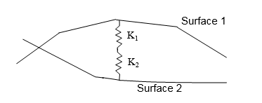
Figure 3. Interface Springs in Series
The equation for the overall interface spring stiffness is:(1) K = s K 1 K 2 K 1 + K 2
Where,
s MathType@MTEF@5@5@+= feaagKart1ev2aaatCvAUfeBSjuyZL2yd9gzLbvyNv2CaerbuLwBLn hiov2DGi1BTfMBaeXatLxBI9gBaerbd9wDYLwzYbItLDharqqtubsr 4rNCHbGeaGqiVu0Je9sqqrpepC0xbbL8F4rqqrFfpeea0xe9Lq=Jc9 vqaqpepm0xbba9pwe9Q8fs0=yqaqpepae9pg0FirpepeKkFr0xfr=x fr=xb9adbaqaaeGaciGaaiaabeqaamaabaabaaGcbaGaam4Caaaa@36EE@
Stiffness scaling factor. Default is 0.2.
K 1 MathType@MTEF@5@5@+= feaagKart1ev2aaatCvAUfeBSjuyZL2yd9gzLbvyNv2CaerbuLwBLn hiov2DGi1BTfMBaeXatLxBI9gBaerbd9wDYLwzYbItLDharqqtubsr 4rNCHbGeaGqiVu0Je9sqqrpepC0xbbL8F4rqqrFfpeea0xe9Lq=Jc9 vqaqpepm0xbba9pwe9Q8fs0=yqaqpepae9pg0FirpepeKkFr0xfr=x fr=xb9adbaqaaeGaciGaaiaabeqaamaabaabaaGcbaGaam4samaaBa aaleaacaaIXaaabeaaaaa@37AD@
Surface 1 Stiffness
K 2 MathType@MTEF@5@5@+= feaagKart1ev2aaatCvAUfeBSjuyZL2yd9gzLbvyNv2CaerbuLwBLn hiov2DGi1BTfMBaeXatLxBI9gBaerbd9wDYLwzYbItLDharqqtubsr 4rNCHbGeaGqiVu0Je9sqqrpepC0xbbL8F4rqqrFfpeea0xe9Lq=Jc9 vqaqpepm0xbba9pwe9Q8fs0=yqaqpepae9pg0FirpepeKkFr0xfr=x fr=xb9adbaqaaeGaciGaaiaabeqaamaabaabaaGcbaGaam4samaaBa aaleaacaaIXaaabeaaaaa@37AD@
Surface 2 Stiffness
K MathType@MTEF@5@5@+= feaagKart1ev2aaatCvAUfeBSjuyZL2yd9gzLbvyNv2CaerbuLwBLn hiov2DGi1BTfMBaeXatLxBI9gBaerbd9wDYLwzYbItLDharqqtubsr 4rNCHbGeaGqiVu0Je9sqqrpepC0xbbL8F4rqqrFfpeea0xe9Lq=Jc9 vqaqpepm0xbba9pwe9Q8fs0=yqaqpepae9pg0FirpepeKkFr0xfr=x fr=xb9adbaqaaeGaciGaaiaabeqaamaabaabaaGcbaGaam4Caaaa@36EE@
Overall interface spring stiffness

The scale factor, s MathType@MTEF@5@5@+= feaagKart1ev2aaatCvAUfeBSjuyZL2yd9gzLbvyNv2CaerbuLwBLn hiov2DGi1BTfMBaeXatLxBI9gBaerbd9wDYLwzYbItLDharqqtubsr 4rNCHbGeaGqiVu0Je9sqqrpepC0xbbL8F4rqqrFfpeea0xe9Lq=Jc9 vqaqpepm0xbba9pwe9Q8fs0=yqaqpepae9pg0FirpepeKkFr0xfr=x fr=xb9adbaqaaeGaciGaaiaabeqaamaabaabaaGcbaGaam4Caaaa@36EE@ , may have to be increased if:

K 1 < < K 2 or K 2 < < K 1

The calculation of the spring stiffness for each surface is determined by the type of elements.

For example:

K 1 = 1 10 K 2 implies K = s 11 K 2 or K = 10 s 11 K 1

Shell Element

If the main interface segment is a set of shell elements, the stiffness is calculated by:(2) K = 0.5 s E t
Where,
E MathType@MTEF@5@5@+= feaagKart1ev2aaatCvAUfeBSjuyZL2yd9gzLbvyNv2CaerbuLwBLn hiov2DGi1BTfMBaeXatLxBI9gBaerbd9wDYLwzYbItLDharqqtubsr 4rNCHbGeaGqiVu0Je9sqqrpepC0xbbL8F4rqqrFfpeea0xe9Lq=Jc9 vqaqpepm0xbba9pwe9Q8fs0=yqaqpepae9pg0FirpepeKkFr0xfr=x fr=xb9adbaqaaeGaciGaaiaabeqaamaabaabaaGcbaGaam4Caaaa@36EE@
Modulus of Elasticity
t MathType@MTEF@5@5@+= feaagKart1ev2aaatCvAUfeBSjuyZL2yd9gzLbvyNv2CaerbuLwBLn hiov2DGi1BTfMBaeXatLxBI9gBaerbd9wDYLwzYbItLDharqqtubsr 4rNCHbGeaGqiVu0Je9sqqrpepC0xbbL8F4rqqrFfpeea0xe9Lq=Jc9 vqaqpepm0xbba9pwe9Q8fs0=yqaqpepae9pg0FirpepeKkFr0xfr=x fr=xb9adbaqaaeGaciGaaiaabeqaamaabaabaaGcbaGaam4Caaaa@36EE@
Shell Thickness

The stiffness does not depend on the shell size.

Brick Element

If the main interface segment is a set of brick elements, the stiffness is calculated by:(3) K = 0.5 s B A 2 V
Where,
B MathType@MTEF@5@5@+= feaagKart1ev2aaatCvAUfeBSjuyZL2yd9gzLbvyNv2CaerbuLwBLn hiov2DGi1BTfMBaeXatLxBI9gBaerbd9wDYLwzYbItLDharqqtubsr 4rNCHbGeaGqiVu0Je9sqqrpepC0xbbL8F4rqqrFfpeea0xe9Lq=Jc9 vqaqpepm0xbba9pwe9Q8fs0=yqaqpepae9pg0FirpepeKkFr0xfr=x fr=xb9adbaqaaeGaciGaaiaabeqaamaabaabaaGcbaGaam4Caaaa@36EE@
Bulk modulus
A MathType@MTEF@5@5@+= feaagKart1ev2aaatCvAUfeBSjuyZL2yd9gzLbvyNv2CaerbuLwBLn hiov2DGi1BTfMBaeXatLxBI9gBaerbd9wDYLwzYbItLDharqqtubsr 4rNCHbGeaGqiVu0Je9sqqrpepC0xbbL8F4rqqrFfpeea0xe9Lq=Jc9 vqaqpepm0xbba9pwe9Q8fs0=yqaqpepae9pg0FirpepeKkFr0xfr=x fr=xb9adbaqaaeGaciGaaiaabeqaamaabaabaaGcbaGaam4Caaaa@36EE@
Segment area
V MathType@MTEF@5@5@+= feaagKart1ev2aaatCvAUfeBSjuyZL2yd9gzLbvyNv2CaerbuLwBLn hiov2DGi1BTfMBaeXatLxBI9gBaerbd9wDYLwzYbItLDharqqtubsr 4rNCHbGeaGqiVu0Je9sqqrpepC0xbbL8F4rqqrFfpeea0xe9Lq=Jc9 vqaqpepm0xbba9pwe9Q8fs0=yqaqpepae9pg0FirpepeKkFr0xfr=x fr=xb9adbaqaaeGaciGaaiaabeqaamaabaabaaGcbaGaam4Caaaa@36EE@
Element volume


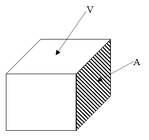
Figure 4. Brick Element

Combined Elements

If a segment is a shell element that is attached to the face of a brick element, the shell stiffness is used.

Interface Friction

TYPE3 interface allows sliding between contact surfaces. Coulomb friction between the surfaces is modeled. The input card requires a friction coefficient. No value (default) defines zero friction between the surfaces.

The friction on a surface is calculated by:(4) Δ F t = K 10 C 1 C 0
Where,
K MathType@MTEF@5@5@+= feaagKart1ev2aaatCvAUfeBSjuyZL2yd9gzLbvyNv2CaerbuLwBLn hiov2DGi1BTfMBaeXatLxBI9gBaerbd9wDYLwzYbItLDharqqtubsr 4rNCHbGeaGqiVu0Je9sqqrpepC0xbbL8F4rqqrFfpeea0xe9Lq=Jc9 vqaqpepm0xbba9pwe9Q8fs0=yqaqpepae9pg0FirpepeKkFr0xfr=x fr=xb9adbaqaaeGaciGaaiaabeqaamaabaabaaGcbaGaam4Caaaa@36EE@
Interface spring stiffness
C 1 C 0
Contact node displacement vector
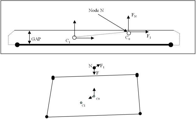

Figure 5. Coulomb Friction
C 0
Contact point at time t
C 1
Contact point at time t + Δ t


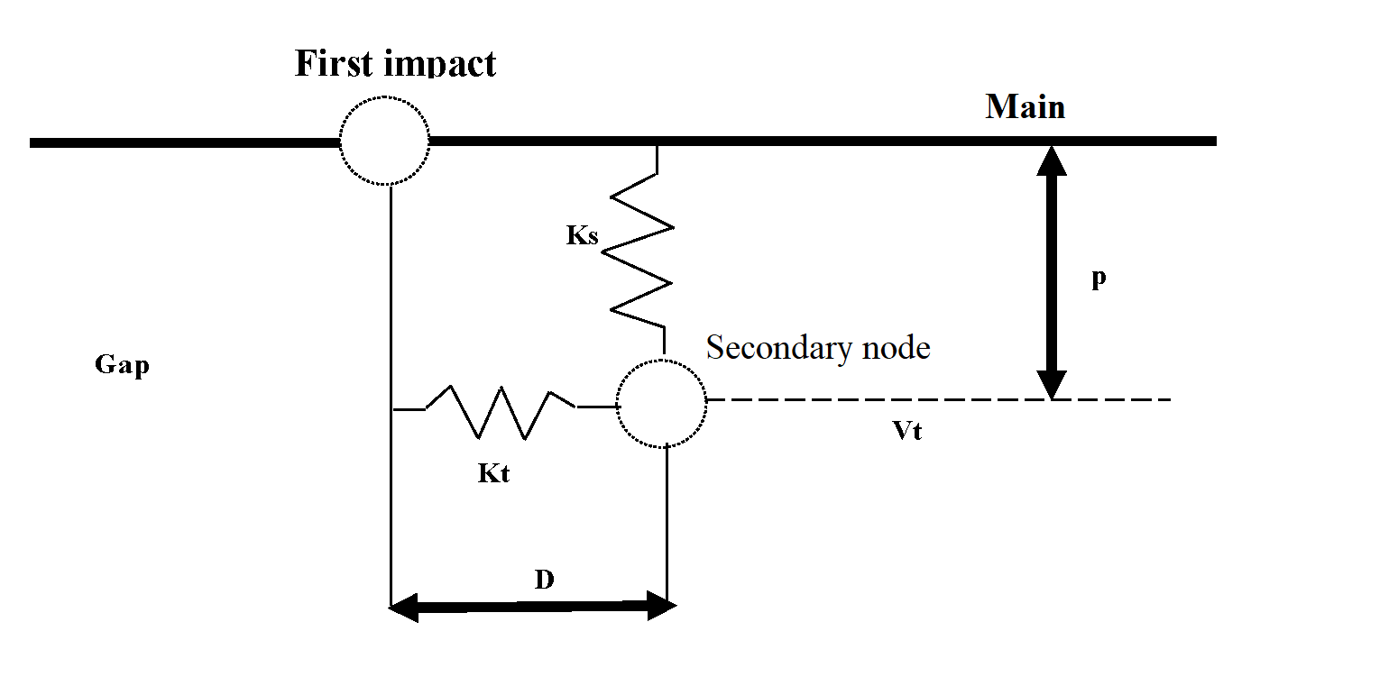
Figure 6. Friction on Interface TYPE3
The normal force computation is given by:(5) F n = K s P
Where,
K s = K 0 ( G a p G a p P )
K 0
Initial interface spring stiffness (as in TYPE5)
The tangential force computation is given by:(6) F t = K t D

Where, K t = K n 10 .

If the friction force is greater than the limiting situation, | F t | > μ | F n | , the frictional force is reduced to equal the limit, | F t | = μ | F n | , and sliding will occur. If the friction is less than the limiting condition, F t μ F n , the force is unchanged and sticking will occur.

Time integration of the frictional forces is performed by:(7) F t n e w = F t o l d + Δ F t
Where,
Δ F t
Result from Equation 4


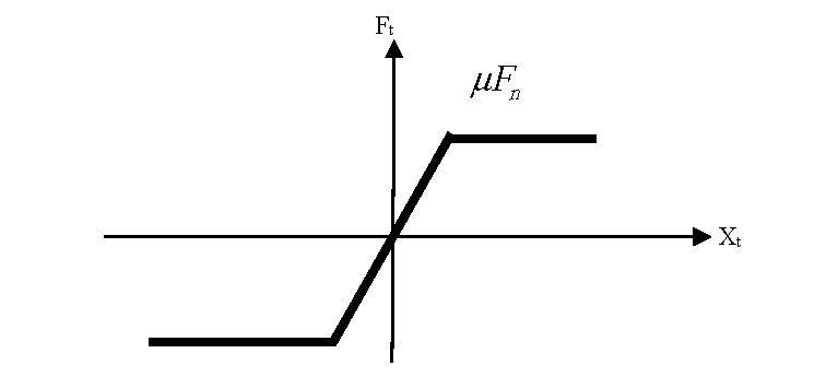
Figure 7. Friction on TYPE3 Interface

Interface Gap

TYPE3 interfaces have a gap that determines when contact between two segments occurs. This gap is user defined, but some interfaces will calculate an automatic default gap.

The gap determines the distance for which the segment interacts with the three nodes. If a node moves within the gap distance, such as nodes 1 and 2, reaction forces act on the nodes.

TYPE3 interface have a gap:
  • Only normal to the segment, as shown in Figure 8
  • On the contact side of the segments, which is defined by the surface normal. The size of the gap defined for certain interface types is critical. If the gap is too small, the solution time step may be dramatically reduced or a node may move across the entire gap in one time step. However, if the gap is too large, nodes not associated with the direct contact may become involved.


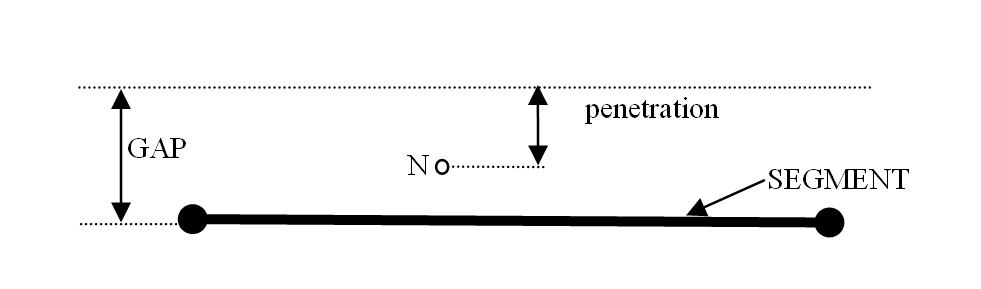
Figure 8. Interface Gap

Examples: Interface Failure

There are a number of situations in which TYPE3 elements may fail. A couple of these are shown below.

Care must be taken when defining contact surfaces with large deformation simulations. If the normal definitions of the contact surfaces are incorrect, node penetration will occur without any reaction from either surface.


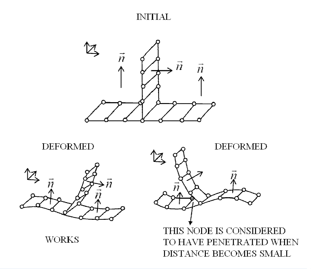
Figure 9. Improper Normal Direction
Referring to Figure 9, the first situation shows the mesh deforming in a way that allows the normals to be facing each other. However, in the second case, the deformation moves two surfaces with normals all facing the same direction, where contact will not be detected. Large rotations can have a similar effect, as shown in Figure 10.


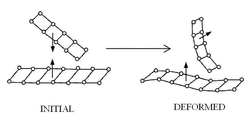
Figure 10. Initial and Deformed Mesh (Before Impact)

Kinematic motion may reposition the mesh so that normals do not correspond. It is recommended that possible impact situations be understood before a simulation is attempted.