General Purpose Interface (/INTER/TYPE7)
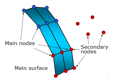
Figure 1. Interface TYPE7
Interface TYPE7 solves all problems and limitations encountered with interface TYPE3 and TYPE5. The search for the closest segment is done via a direct search algorithm; therefore, there are no search limitations and all possible contacts are found. The energy jumps induced by a node impacting from the shell edges are removed by the use of a cylindrical gap around the edges.
Finally, the main advantage of interface TYPE7 is that the stiffness is not constant and increases with penetration preventing the node from going through the shell mid-surface. This solves many bad contact treatments (common when using either interface TYPE3 or TYPE5).
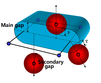
Figure 2. Gap in Interface TYPE7
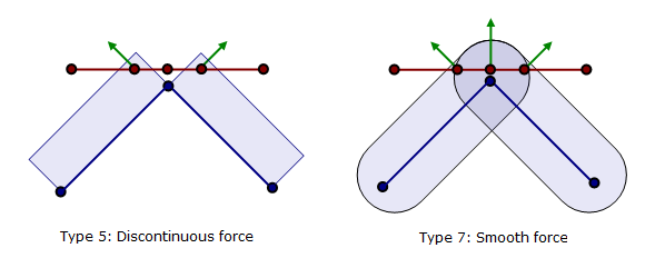
Figure 3. Sliding Between Segments
Contrary to interface TYPE3 and TYPE5, a variable gap in space is available. Depending on option Igap, variable gap is computed for each impact as the sum of the main element gap (gm) and the secondary node gap (gs).
| Element | Main Element Gap (gm) | Secondary Node Gap (gs) |
|---|---|---|
| SHELL |
t: thickness of the main segment |
t: largest thickness of shell elements connected to the secondary node |
| BRICK | ||
| TRUSS and BEAM | Non-applicable |
S: cross section |
If a minimum gap for impact activation (Gapmin) is also used, the computed variable gap cannot be smaller than the minimum value. It is also possible to apply a scale factor to the gap and define a maximum gap value.