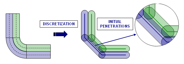
In an FE model, initial penetrations are very common, are unavoidable and result from the
discretization during the meshing process (Figure 1). Figure 1. Initial Penetrations Due to Discretization
Inacti
Special treatment for initial penetrations can be accomplished through the use of the Inacti flag. It is possible to remove penetrated nodes from the interface or to remove
the main segments relating to the penetrated nodes. Both treatments allow getting
rid of initial penetrations very easily, but they may lead to poor results if the
number of penetrated nodes is large.
Setting Inacti
to 3 allows Radioss Starter to automatically modify the
coordinates of penetrated nodes to avoid initial penetrations. Special care must be
taken when doing so, since this operation can lead to initially constrained
springs.
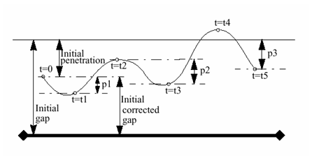
It is also possible to obtain a variable gap in time by setting Inacti to 5. The illustration Figure 2 explains how the effective gap is updated taking into account the
previous penetrations. Figure 2. Variable Gap in Time
At t=0, if a node is initially penetrated, its gap is automatically corrected. Then this
"initial corrected gap" will be increased every time the node is
moving away from the main segment. This option is mainly used for unfolding the
airbag, it allows a decent time step at the beginning of the unfolding, whereas
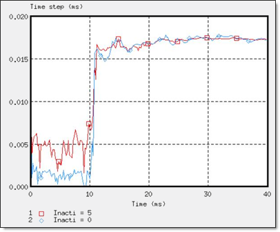
nodes are all highly penetrated. Figure 3. Time Step Using Inacti=5
To avoid high frequency effects Inacti = 6 is recommended instead of Inacti =5.
Fpenmax
Fpenmax
(maximum fraction of initial penetration), is used to deal with big initial
penetration. Node stiffness will be deactivated, if , whatever the value of Inacti.
Igap3 + %mesh_size
With Igap= 3
and %mesh_size, the size of the mesh can be taken into account to
avoid initial penetrations. In this case, the variable gap is computed
as:(1)
Where,
Length of the smaller edge of element
Length of the smaller edge of elements connected to the secondary
node
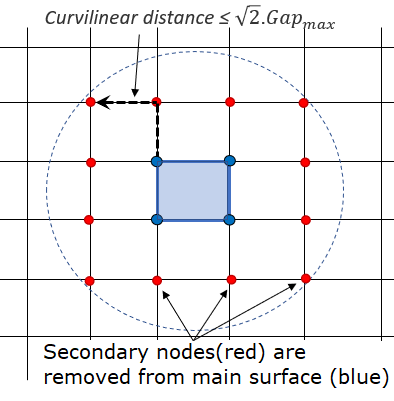
Irem_gap
The option Irem_gap is used to deactivate secondary nodes which close
(Curvilinear ) to elements. This option is useful for self-impact
contact when mesh size is very small. Figure 4. -1: Irem_gap Definition
Note: When dealing with initial penetrations, it is strongly
advised to remove initial penetrations during the creation of the FE model,
using pre-processing tools like HyperMesh and
HyperCrash depenetrators.