This interface is used to simulate symmetric impacts between two surfaces.
Both surfaces are defined through the use of oriented segments; therefore, contacts can only
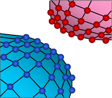
occur on one side. Each node on both surfaces is considered as a secondary node, and
each surface is considered as a main segment. Figure 1. Interface TYPE3
Contrary to interface TYPE5, interface TYPE3 has two main surfaces; therefore, the contact
algorithm is performed twice. The first pass solves the penetration of nodes from
the first surface with respect of the second surface. The second pass solves the
penetration of nodes from the second surface with respect of the first surface. This
leads to higher accuracy compared to interface TYPE5, but more CPU time is
needed.
When contact is detected, an elastic spring is added and the spring stiffness is calculated using
both surfaces stiffness. Based on material and geometric properties, stiffness is
attributed to each surface, then the overall interface stiffness is
computed:(1)
The default value for the stiffness scale factor(s) is 0.2, for stability reason this value
should not be modified. However, if the ratio of over is greater than 100 (or lower than 0.01), it is
recommended to increase the stiffness scale factor to avoid too many penetrations.
The spring stiffness is constant, allowing secondary nodes to pass through the
mid-plane of the main segment.
This interface does not enable auto-contact simulation, as a node cannot belong to both
surfaces.
Note: This interface is mainly used for shell plates
initially in contact. If the two plates are modeled with a gap between the two
meshes, it is better to use interface TYPE7; unless, if the two plates are
modeled without a gap, interface TYPE3 is a good choice.