RD-E: 2203 Ditching using Multi-Domain for SPH and ALE
Impact of a simple object on water using Multi-Domain to approach SPH and ALE.
The problem consists of a simple object falling into water simulating the ditching of a helicopter.
Options and Keywords Used
- /SUBDOMAIN in Multi-Domain
- /RAD2RAD/ON in Engine
Input Files
- SPH (Multi-Domain)
- <install_directory>/hwsolvers/demos/radioss/example/22_Ditching/Ditching_Multi_Domain_SPH/*
- ALE (Multi-Domain)
- <install_directory>/hwsolvers/demos/radioss/example/22_Ditching/Ditching_Multi_Domain_ALE/*
Model Description
Unit: mm, ms, KN, GPa, kg
Use Example 2201 as SPH ditching and Example 2202 as ALE ditching, then add Multi-Domain approach in SPH ditching and ALE ditching
Model Method of Multi-Domain (Single Input Format) Approach
- Setup /SUBDOMAIN in Starter:
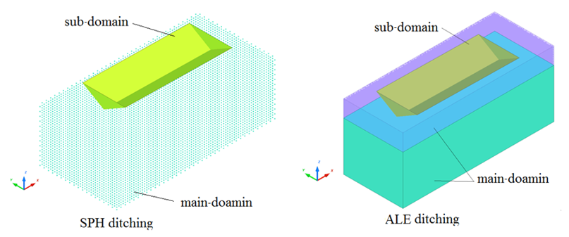
- Use /SUBDOMAIN to define sub-domain. In this example part ID 19 is defined as sub-domain.
- For SPH ditching:

Figure 1. - For ALE ditching:

Figure 2.Note: Thesubdomain_title"SPH_SubDomain" (or "ALE_SubDomain") must be the same as sub-domain Engine name SPH_SubDomain_0001.rad (or ALE_SubDomain_0001.rad).
Figure 3. Domain Description in Multi-Domain Approach
- Setup in two Engine files:
- First Engine file (main-domain):
- Take the Engine of Mono-Domain and insert /RAD2RAD/ON keyword.
- Free element time step control for ALE or free nodal time step control for SPH in the first Engine file.
- Second Engine file (sub-domain):
- Take the Engine of Mono-Domain and insert /RAD2RAD/ON keyword.
- Update the Engine name and also the run name in /RUN. They
must match the
subdomain_titlein Starter /SUBDOMAIN. - Set the Lagrange parts (part ID 19) specific time step control

Figure 4. Multi-Domain Setup in Starter and Engine (SPH ditching as example) - First Engine file (main-domain):
Contact Between Main-domain and Sub-domain
As of Radioss version 14.0, Starter automatically creates coupling links between domains with Multi-Domain Single Input Format. In SPH, ditching using /INTER/TYPE7 coupling links between Lagrange sub-domain and SPH main-domain are automatically created. In ALE, ditching using /INTER/TYPE18 coupling links between Lagrange sub-domain and ALE main-domain are automatically created.
Results
Results between Mono-Domain and Multi-Domain
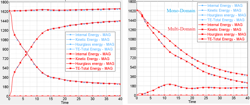
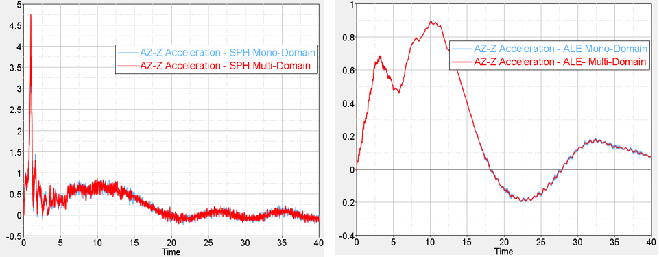
To compare the results between Mono-Domain and Multi-Domain, take the model with 11m/s in initial velocity in SPH ditching and in ALE ditching.
- Energy comparison between Mono-Domain and Multi-Domain

Figure 5. Left: SPH Ditching; Right: ALE Ditching - Acceleration comparison between Mono-Domain and Multi-Domain

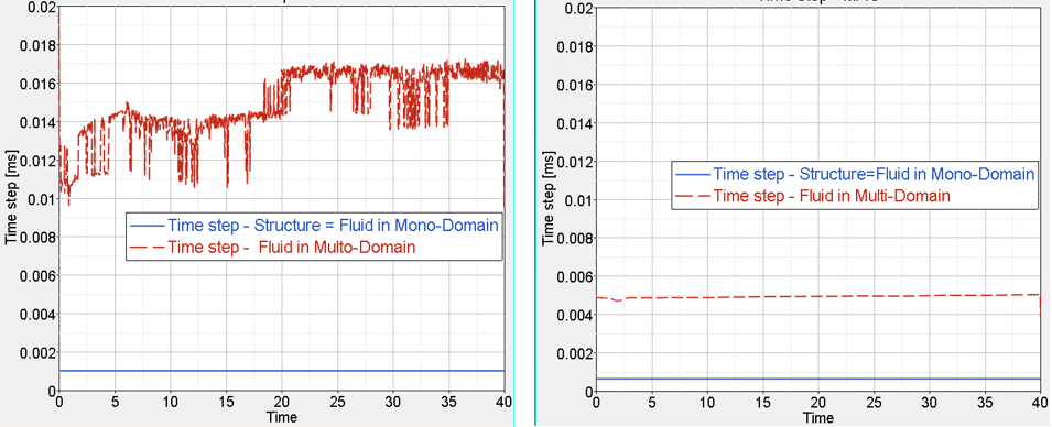
Figure 6. Left: SPH Ditching; Right: ALE DitchingThe time step in Multi-Domain is much bigger than in Mono-Domain.
- Time step comparison between Mono-Domain and Multi-Domain

Figure 7. Left: SPH Ditching; Right: ALE DitchingTheoretical speedup α formula:(1) Where,- Number of elements
- Number of cycles
- Element average time cost/cycle
Speedup α could also be formulated with following factors:- Relative element number:
(2) - Relative time step (relative cycle numbers):
(3) with- Time step
- Relative cost per cycle:
(4) - Lagrange shell
- = 1
- Lagrange solid
- ~ 3
- ALE solid
- ~ 6
- SPH cell
- ~ 15
Then speedup α will be:(5) Elapsed times:
Figure 8. SPH Ditching
Figure 9. ALE DitchingAfter comparing the elapsed time, observe Multi-Domain FSI speedups ranging from 6 times to 9 times of the Mono-Domain.
Conclusion
- The Multi-Domain is particularly adapted to FSI simulations involving a large amount of either ALE elements or SPH cells which the time steps are significantly higher than the one in the much smaller in terms of elements of the Lagrange structure
- The easiness of setup makes the Multi-Domain applied to FSI much simpler than when applied to purely Lagrange models where the cross-domain contacts need to be minimized as long as this aspect is not automated
- Due to this setup easiness the Multi-Domain results in FSI give less possibility to deviations when compared to classical mono-domain results
- FSI simulations often involving large ALE or SPH domains with high time steps the Multi-Domain speedups are significantly higher than in pure Lagrange simulations like in Crash
Comments
- For Multi-Domain FSI there is no need to minimize the contacts in TYPE7 interface (SPH) or in TYPE18 or TYPE22 interfaces (ALE) between Fluid and Structure whereas it is needed in pure Lagrange Multi-Domain.
- For Multi-Domain FSI it is advised to use for the main-domain a free element time step with a scaling factor of 0.5 for ALE and a free nodal time step with a scaling factor of 0.6.
- When Lagrange parts are assembled using tied contact interface TYPE2, then poor performances may
occur with Spotflag = 0 or 1.
- Set Spotflag = 26 to switch from kinematic to penalty formulation to solve the problem. In such cases (Spotflag = 26) contacts become permissive depending on assigned contact stiffness. It is also recommended to check the contacts quality in animation results to make sure no significant penetrations occur.