RD-E: 2201 Ditching using SPH (Mono-Domain)
Impact of a simple object on water.
The problem consists of a simple object falling into water simulating the ditching of a helicopter.
Options and Keywords Used
- SPH modeling and hexagonal net
- Hydrodynamic viscous fluid law (/MAT/LAW6 (HYDRO or HYD_VISC)) and impact on water modeling
- Interface (/INTER/TYPE7)One type of contact occurs in the simulation. Contact between the skin structure (shell finite elements) and the water (SPH cells) is modeled using a sliding interface (TYPE7). The gap between the surface skin and the SPH cells is equal to 3 mm. After optimization, a scale factor on the Penalty stiffness interface equal to 0.1 is used for controlling the interface forces between the rigid object and the water.
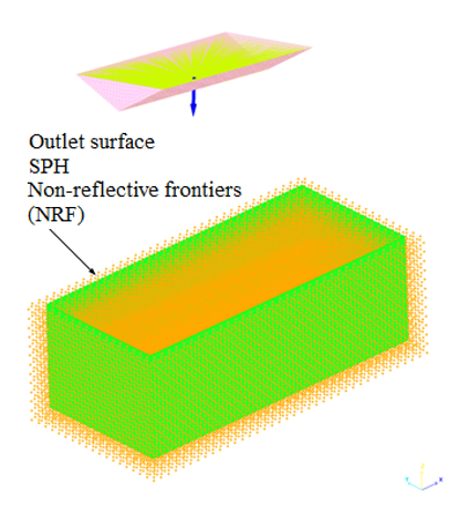
Figure 1. SPH Outlet Boundary Surface Non-reflective Frontiers (NRF) (green) - Rigid body (/RBODY)
The object is modeled using a rigid body, and a mass of 23.0422 kg is added to the rigid body's main node (ID: 287002).
- Initial velocity (/INIVEL)
An initial velocity, in accordance with the Z-axis, is set on the rigid body's main node and its value is set successively at 3.5 m/s, 6.8 m/s and 11 m/s.
- Accelerometer (/ACCEL)
An accelerometer is set on the rigid body's main node.
- Gravity (/GRAV)
A gravity load gz = -9.81 m.s-2 is applied to the object.
- Interface (/INTER)
- SPH outlet (/SPH/INOUT)
The parallelepiped water mesh is surrounded on five faces by Outlet SPH boundary frontier absorbing conditions. A control surface is placed at a distance equal to 2 x ho inside the water. This surface shown in green (Figure 1), is oriented so that its normal vector points face the interior of the domain. On this outlet surface, specific non-reflective frontiers (NRF) are applied to the SPH cells.
Input Files
- Impact_velocity=3.5m/s
- <install_directory>/hwsolvers/demos/radioss/example/22_Ditching/Ditching_Mono_Domain_SPH/v_35/*
- Impact_velocity=6.8m/s
- <install_directory>/hwsolvers/demos/radioss/example/22_Ditching/Ditching_Mono_Domain_SPH/v_68/*
- Impact_velocity=11m/s
- <install_directory>/hwsolvers/demos/radioss/example/22_Ditching/Ditching_Mono_Domain_SPH/v_110/*
Model Description
Units: mm, ms, KN, GPa, kg.
Impact of a triangular section object on water is performed and the results are compared qualitatively 2, also using the experimental data obtained from the Politecnico di Milano. 1
The computation is performed using several impact velocities: 3.5 m/s, 6.8 m/s and 11 m/s.
- Material Properties
- Initial density
- 7.8 x 10⁻⁶ kg.mm-3
- Young's modulus
- 206.9 GPa
- Poisson ratio
- 0.3
- Material Properties
- Initial density
- 1 x 10⁻⁶ kg.mm-3
- Kinematic viscosity
- 0
- Pressure cutoff
- -0.0001 GPa
- Pressure shift
- 0 GPa
- C0
- 0 GPa
- C1
- 2.199 GPa
- C2
- 5.351 GPa
- C3
- 7.324 GPa
- C4
- 0 GPa
- C5
- 0 GPa
- Initial energy/unit of volume
- 0 mJ/mm3
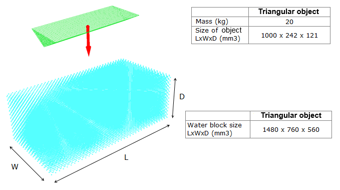
Figure 2. Problem Data
Model Method
The object is modeled using shell elements with an average mesh size of 15 x 15 mm2.
The water is modeled using SPH particles having a hexagonal compact net with a smoothing length "ho" equal to 28.2843 mm. Each particle of the net represents a volume equal to 16 mm3 and weighs 16 g. This part uses 36075 SPH cells.
The size of the water block is adapted to the shape of the object for the purpose of reducing the model's size and the simulation's CPU time.
Results
Output Pressure
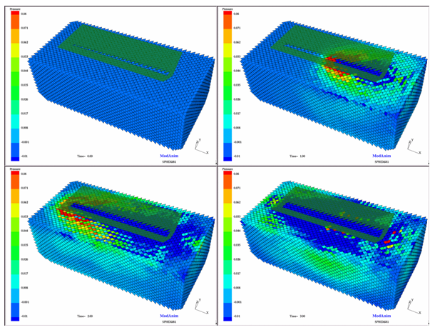
Figure 3. Ditching Simulation (from the beginning to 3 ms)
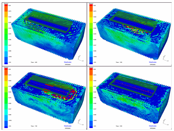
Figure 4. Ditching Simulation (from 4 ms to 9 ms)
Output Acceleration
For the object, an accelerometer is set on the main node of the corresponding rigid body. The acceleration values expressed in g units are compared to both the experimental values 1 and the analytic solution proposed by Von Karman. 2 The signal is filtered using a CFC 60 (-3db) filter frequency after calculation. The filtering reduces discrepancy between the peaks.
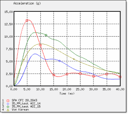
Figure 5. Deceleration of the Wedge for an Impact Velocity of 3.5 m/s
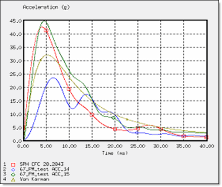
Figure 6. Deceleration of the Wedge for an Impact Velocity of 6.8 m/s
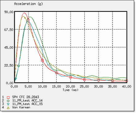
Figure 7. Deceleration of the Wedge for an Impact Velocity of 11 m/s
For these three cases, the SPH approach using the OUTLET SPH boundary conditions indicates a good deceleration. For an impact velocity nearing the 8 m/s of the helicopter ditching configuration, the deceleration is in correlation with the experimental data 1 and also with the analytic solution proposed by Von Karman. 2
Conclusion
The simulations show that the SPH approach using the OUTLET option, allows the ditching of simple objects to be modeled without any numerical problems.
The SPH and OUTLET results are very close to the experimental test results and also to the analytical solution. In conclusion, to achieve ditching simulations with the correct results, it is necessary to model the water block using the SPH method with the OUTLET boundary conditions.