/MAT/LAW57 (BARLAT3)
Block Format Keyword This law describes plasticity hardening by a user-defined function and can be used only with shell elements.
This is an elasto-plastic orthotropic law for modeling anisotropic materials in forming processes especially aluminum alloys. This material law must be used with property set type /PROP/TYPE9 (SH_ORTH) or /PROP/TYPE10 (SH_COMP).
Format
| (1) | (2) | (3) | (4) | (5) | (6) | (7) | (8) | (9) | (10) |
|---|---|---|---|---|---|---|---|---|---|
| /MAT/LAW57/mat_ID/unit_ID or /MAT/BARLAT3/mat_ID/unit_ID | |||||||||
| mat_title | |||||||||
| E | |||||||||
| fct_IDE | Einf | CE | |||||||
| r00 | r45 | r90 | Chard | m | |||||
| (1) | (2) | (3) | (4) | (5) | (6) | (7) | (8) | (9) | (10) |
|---|---|---|---|---|---|---|---|---|---|
| fct_IDi | Fscalei | ||||||||
Definitions
| Field | Contents | SI Unit Example |
|---|---|---|
| mat_ID | Material identifier (Integer, maximum 10 digits) |
|
| unit_ID | Unit Identifier (Integer, maximum 10 digits) |
|
| mat_title | Material title (Character, maximum 100 characters) |
|
| Initial density (Real) |
||
| E | Young's modulus (Real) |
|
| Poisson's ratio (Real) |
||
| fct_IDE | Function identifier for the scale factor
of Young's modulus, when Young's modulus is function of the plastic strain. 11 Default = 0: in this case the evolution of Young's modulus depends on Einf and CE. (Integer) |
|
| Einf | Saturated Young's modulus for infinitive
plastic strain. (Real) |
|
| CE | Parameter for Young's modulus
evolution. (Real) |
|
| r00 | Lankford parameter 0 degree. Default = 1.0 (Real) |
|
| r45 | Lankford parameter 45 degrees. Default = 1.0 (Real) |
|
| r90 | Lankford parameter 90 degrees. Default = 1.0 (Real) |
|
| Chard | Hardening coefficient.
(Real) |
|
| m | Barlat parameter.
(Real) |
|
| Failure plastic strain. Default = 1.0 x 1030 (Real) |
||
| Tensile failure strain at which stress
starts to reduce. Default = 1.0 x 1030 (Real) |
||
| Maximum tensile failure damage strain at
which the stress in element is set to zero. Default = 2.0 x 1030 (Real) |
||
| fct_IDi | Plasticity curves
ith function identifier. (Integer) |
|
| Fscalei | Scale factor for
ith function. Default set to 1.0 (Real) |
|
| Strain rate for
ith function. (Real) |
Example (Steel)
#RADIOSS STARTER
#---1----|----2----|----3----|----4----|----5----|----6----|----7----|----8----|----9----|---10----|
/UNIT/1
unit for mat
                  g                  mm                  ms
#---1----|----2----|----3----|----4----|----5----|----6----|----7----|----8----|----9----|---10----|
#-  2. MATERIALS:
#---1----|----2----|----3----|----4----|----5----|----6----|----7----|----8----|----9----|---10----|
/MAT/LAW57/1/1
Steel
#              RHO_I
                .008
#                  E                  NU
              206000          .300000012
#  fct_IDE                         E_INF                  CE
         0                             0                   0
#                r00                 r45                 r90              C_hard                   m
                1.79                1.51                2.27                   0                   0
#           EPSP_max               EPS_T               EPS_M
                   0                   0                   0
#   fct_ID                      Fscale_i               EPS_i
         5                             0                   0
#---1----|----2----|----3----|----4----|----5----|----6----|----7----|----8----|----9----|---10----|
#-  3. FUNCTIONS:
#---1----|----2----|----3----|----4----|----5----|----6----|----7----|----8----|----9----|---10----|
/FUNCT/5
function_5
#                  X                   Y
                   0                 157
                  .1                 320
                  .5                 480
                 1.2                 600
#---1----|----2----|----3----|----4----|----5----|----6----|----7----|----8----|----9----|---10----|
#ENDDATA
/END
#---1----|----2----|----3----|----4----|----5----|----6----|----7----|----8----|----9----|---10----|
Comments
- The anisotopic yield criteria
F for plane stress is defined by:
(1) Where,
is the yield stress
and
- Angles for Lankford parameters are defined with respect to orthotropic direction 1.
The material constants a, c, h, and
p are obtained from the three Lankford parameters:
(2) Material constant p is calculated by solving:(3) - If the last point of the first (static) function equals 0 in stress, the default value of is set to the corresponding value of .
- If (plastic strain) reaches , in one integration point, the corresponding shell element is deleted.
- If the largest principal strain
, the stress is reduced using the following
relation:
(4) - If , the stress is reduced to 0 (but the element is not deleted).
- The maximum number of curves is 10.
- If , the yield is interpolated between fn and fn-1.
- If , function f1 is used.
- Above
, yield is extrapolated.
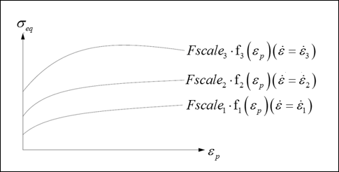
Figure 1. - The evolution of
Young's modulus:
- If fct_IDE > 0, the curve defines a scale factor for Young's modulus evolution with equivalent
plastic strain, which means the Young's modulus is scaled by the function
:
(5) The initial value of the scale factor should be equal to 1 and it decreases.
- If fct_IDE = 0, the Young's modulus is calculated as:
(6) Where, E and Einf are respectively the initial and asymptotic value of Young's modulus, and is the accumulated equivalent plastic strain.
Note: If fct_IDE = 0 and CE = 0, Young's modulus, E is kept constant.
- If fct_IDE > 0, the curve defines a scale factor for Young's modulus evolution with equivalent
plastic strain, which means the Young's modulus is scaled by the function
: