RD-E: 5101 Size Optimization of a B-Pillar
This example defines a crash test on B-Pillar. The optimization objective is to minimize the mass of the B-Pillar by changing the shell thickness. The intrusion, which is defined by the optimization constraint is required to not be larger than the original model, to keep the passenger safe.
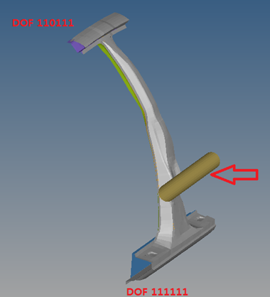
Figure 1.
The setup of optimization in Radioss requires an extra input file apart from the usual Starter and Engine input files. The required file is an optimization input file named <name>.radopt (the Starter and Engine files are named <name>_0000.rad and <name>_0001.rad, respectively). The <name>.radopt file defines optimization entities such as the optimization objective, optimization constraints, design variables, optimization responses and so on.
Options and Keywords Used
- Optimization objective (/DESOBJ)
- Optimization design variable (/DESVAR)
- Relate design variables to analysis model properties (/DVPREL1)
- Optimization design response (/DRESP1)
- Optimization design constraint (/DCONSTR)
- Material law (/MAT/LAW36 (PLAS_TAB))
- Shell property (/PROP/TYPE1 (SHELL))
- Initial velocity (/INIVEL)
- Interface (/INTER/TYPE7)
- Rigid body (/RBODY)
Input Files
- B-Pillar (Thickness Optimization)
- <install_directory>/hwsolvers/demos/radioss/example/51_RADIOSS_Optimization/Size_Optimization
Model Description
Units: mm, s, ton, N, and MPa
- Objective: Minimize mass
- Constraint: Maximum displacement of node 2021524 in Y direction (inside
reinforcement) < 19.7 [mm]
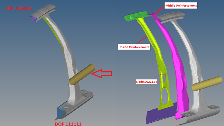
Figure 2. Problem Description - Design variables:
- Shell thickness of the middle reinforcement - allowable range [0.5mm, 3.0mm]
- Shell thickness of the inside reinforcement - allowable range [0.5mm, 3.0mm]
Detailed Optimization Setup
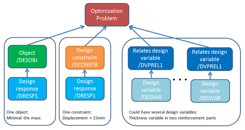
Figure 3. Radioss Optimization Setup
Optimization Objective
/DESOBJ is used to define optimization objective. In this example, it defines the minimal response #1.
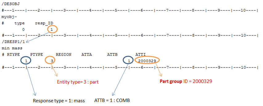
Figure 4. Optimization Objective Setup in Radioss Optimization
Optimization Constraint
In this example, you want to constrain the intrusion to not be larger than the original model (before optimization). In the original model, max. y-displacement in node 2021524 is 19.7mm. Define this value as cmax in /DCONSTR and in response 2, define 19.7 as the max. y-displacement (with RTYPE=5, ATTA=7) in node 2021524 (with PTYPE=1, ATTI=2021524).
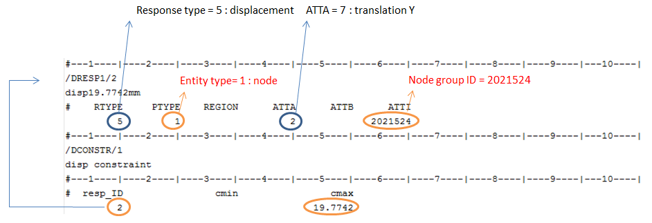
Figure 5. Optimization Constraint Setup in Radioss Optimization
Design Variable
/DESVAR is used to define design variables and /DVPREL1 to relate design variables to analysis model property.
Two different design variables are defined: One for part 2000327 and one for part 2000329
- In /DESVAR with the range [0.5,3.0] - this will be used
in /DVPREL1.
In /DVPREL1 with prop_typ and prop_fid the above variable can be used for shell thickness, and with prop_ID the thickness in shell property 2000327 will be used in the optimization run.
- COEF1 in /DVPREL1. In each
iteration, Pi (the thickness value) will be
equal to , where which is defined in
/DESVAR.
(1) 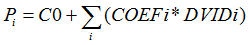
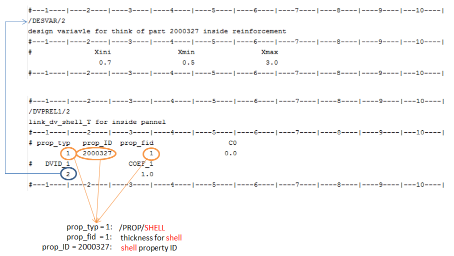
Figure 6. Design Variable Setup in Radioss Optimization
Radioss Options Used
/INIVEL and /INTER/TYPE7 are also used.
Use /INIVEL to optimize the B-Pillar under same initial kinetic energy.
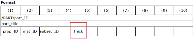
Figure 7. /PART Card in Radioss Starter File
Results
- The latest design provides the best results. Verify whether the result is
feasible or not. In the *.out file
(Neon-b_pillar.out) this data is at end of each
iteration.
FEASIBLE DESIGN (ALL CONSTRAINTS SATISFIED) - indicates that the design is good.
INFEASIBLE DESIGN (AT LEAST ONE CONSTRAINT VIOLATED). - indicates that the design variable definition needs to be checked/improved.
This information can also be found in the output file hwsolver.mesg.
- In the *.out file (Neon-b_pillar.out), check/verify the optimization definition. Objective Function: Minimize Combined Mass, Run Type: Sizing Optimization and so on.
- By running the Optimization in Radioss, an equivalent OptiStruct model will also be automatically created and named *.fem (Neon-b_pillar.fem).

Figure 8. Optimized Results in Each Iterations in *eslout File
In the original model, the mass of the two parts is 3.0011e-3[Ton] and the optimized mass for these two parts is 2.4158e-3[Ton]. The mass is reduced by approximately 19.5%.
The thickness of part #2000327 is 1.328mm and the optimized thickness is 0.5539mm. The thickness is reduced.
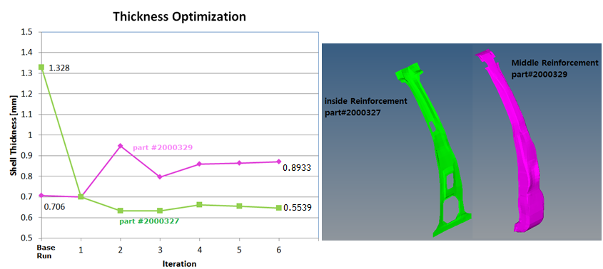
Figure 9. Optimized Results of Shell Thickness of Two Reinforcement Parts
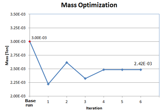
Figure 10. Optimized Results of Total Mass of Two Reinforcement Parts
In the last iteration, the mass was reduced to 2.4158e-3[Ton]. This new design still meets the constraint (< 19.7[mm]), defined in /DCONSTR.
In node 2021524, the max. y-displacement:
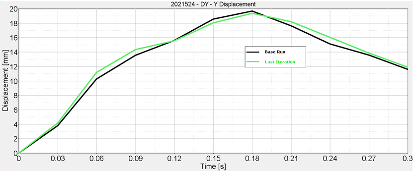
Figure 11. y-displacement on Node 2021524 in Original Model and Optimized Model