Turbulator Passage Elements
Turbulator Element General Description & Quick Guide
![]()
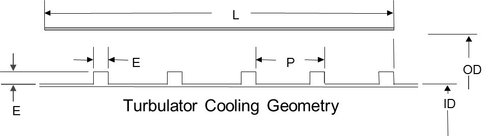
There Turbulator element models the frictional pressure drop across the Turbulated passage. This element can be found under both “Compressible Gas Elements” & “Incompressible Liquid Elements”. The geometric inputs like inner diameter (ID), outer diameter (OD), passage length(L), Rib Pitch (P), Rib height (E) are mandatory inputs. Apart from these, inputs related to friction are required if friction options are selected. Descriptions about each input is described below in “Turbulator Element Inputs” section.
Turbulator Element Inputs
Table of the inputs specific for the Turbulator Element. Transition Element Theory
| Entries Common to All Component Types | ||
|---|---|---|
| Index | Variable | Description |
| 1 | Cross-Section Shape (CS_MODE) |
Cross-section shape allows user to specify geometry in four different ways. 1: Annular with Inner and Outer Diameter specified (Internally, the solver computes area and perimeter.) 2: Circular with Area specified (Internally, the solver computes diameter and perimeter.) 3: Circular with Diameter specified (Internally, the solver computes area and perimeter) 4: Arbitrary Shape with Area as well as Hydraulic Diameter specified. (Internally, the solver computes the perimeter.) |
| 2 | Inner Diameter (INNER_DIAM) |
Inner Annulus Diameter This is needed only when CS_MODE=1. |
| 3 | Outer Diameter (OUTER_DIAM) |
Outer Annulus Diameter (inches) This is needed only when CS_MODE=1. |
| 4 | Cross-section Area (AREA) |
Cross-section area If area is non-constant, then AREA is exit area. This field is needed only when CS_MODE=2 or 4. |
| 5 | Hydraulic Diameter (HYD_DIAM) |
Diameter (or Hydraulic Diameter for non-circular cross-sections) If diameter is non-constant, then this is exit diameter. This field is need only when CS_MODE=3 or 4. |
| 6 | Length (LENGTH) |
Short Passage Length Since friction losses a modelled as occurring at the exit, properties (area, velocity, pressure, etc.) should not vary too much from inlet to exit. Thus, the Short Passage is good for modeling small L/D channels. For longer L/D channels, the tube element is preferred. |
| 7 | Wall texture (WALL_TYPE) |
Wall texture option 1: Smooth or Rough wall (uses Colebrook-White) 2: Turbulated Wall (uses Webb) |
| 8 | Rib Height (RIB_HEIGHT) |
Turbulator Rib Height (inches) Needed if WALL_TYPE=2 |
| 9 | Rib Pitch (RIB_PITCH) |
Center-to-center distance between turbulator ribs (inches) Needed if WALL_TYPE=2 |
| 10 | Roughness (ROUGHNESS) |
Roughness value When FRIC_MODE=1 (friction calculated with Swamee-Jain approximation to Colebrook-White), roughness can be provided. Sand-grain roughness is the default type, since that is what Moody, Colebrook-White, Swamee, etc. are based on. |
| 11 | Friction Mode (FRIC_MODE) |
Friction options 0: No friction 1: Fixed Smooth/Rough wall Friction Coefficient; Turbulator Friction Coefficient = 0.0 2: Colebrook-White Smooth/ Rough wall Friction Coefficient; Turbulator Friction Coefficient = 0.0 3: Fixed Smooth/Rough wall Friction Coefficient; Fixed Turbulator Friction Coefficient 4: Colebrook-White Smooth/ Rough wall Friction Coefficient; Fixed Turbulator Friction Coefficient 5: Fixed Smooth/Rough wall Friction Coefficient; Webb Turbulator Friction Coefficient 6: Colebrook-White Smooth/ Rough wall Friction Coefficient; Webb Turbulator Friction Coefficient |
| 12 | Constant Smooth/Rough Wall Friction Coefficient (FRIC_SMOOTH) | When FRIC_MODE=1, 3, 5, or 7 (User-specified smooth/rough friction), Darcy Friction Coefficient should be provided. |
| 13 | Constant Turbulator Friction Coefficient (FRIC_TURB) | When FRIC_MODE=3 or 4 (User-specified turbulator friction), Darcy Friction Coefficient should be provided. |
| 14 |
Friction multiplier for smooth/rough friction coefficient (FM_SMOOTH) |
User-specified multiplier for friction coefficient on the smooth/rough wall This should only be used with calculated friction values. FMULTs are often used to account for roughness effects, so FMULT should probably be used only when ROUGHNESS =0. (Can be 0 or higher) |
| 15 |
Friction multiplier for turbulator friction coefficient (FM_TURB) |
User-specified multiplier for friction coefficient on turbulators This should only be used with calculated friction values. (Can be 0 or higher) |
| 16 | Portion of Ustrm Chamb. Dyn. Head Lost (DQ_IN) | Inlet dynamic head loss. Refer General solver theory sections for more details about this input |
| 17 | Rotor Index (RPMSEL) |
Reference rotor index for user-supplied swirl. Stationary (Database Value = 0.0) Rotor 1 (Database Value = 1.0): Points to general data Shaft 1 Rotor Speed. Rotor 2 (Database Value = 2.0): Points to general data Shaft 2 Rotor Speed Rotor 3 (Database Value = 3.0): Points to general data Shaft 3 Rotor Speed Rotates with Air (database Value = -1.0): Element RPM is based on upstream fluid RPM |
| 18 | Radius (RAD) |
Radius (in). Radial distance between the orifice inlet center and the engine centerline. (Do not use zero unless the orifice is not rotating) |
| 19 | Element Inlet Orientation: Tangential Angle (THETA) |
Angle between the element centerline at the entrance of the element and the reference direction. If the element is rotating or directly connected to one or more rotating elements, the reference direction is defined as parallel to the engine centerline and the angle is the projected angle in the tangential direction. Otherwise, the reference direction is arbitrary but assumed to be the same as the reference direction for all other elements attached to the upstream chamber.
THETA for an element downstream of a plenum chamber has no impact on the solution except to set the default value of THETA_EX. (See also THETA_EX) |
| 20 | Element Inlet Orientation: Radial Angle (PHI) |
Angle between the element centerline at the entrance of the element and the THETA direction. (spherical coordinate system)
PHI for an element downstream of a plenum chamber has no impact on the solution except to set the default value of PHI_EX. (See also PHI_EX) |
|
21 22 23 |
Exit K Loss: Axial (K_EXIT_Z) Tangential (K_EXIT_U) Radial (K_EXIT_R) |
Head loss factors in the Z, U, and R directions based on the spherical coordinate system of theta and phi. (Default value provides no loss).
Refer General solver theory sections for more details about this input |
| 24 | Element Exit Orientation: Tangential Angle (THETA_EX) |
Angle between the orifice exit centerline and the reference direction. THETA_EX is an optional variable to be used if the orientation of the element exit differs from that of the element inlet.
The default value (THETA_EX = -999) will result in the assumption that THETA_EX = THETA.
Other values will be interpreted in the manner presented in the description of THETA. |
| 25 | Element Exit Orientation: Radial Angle (PHI_EX) |
Angle between the orifice exit centerline and the THETA_EX direction.
PHI_EX is an optional variable to be used if the orientation of the element exit differs from that of the element inlet.
The default (PHI_EX = -999) will result in the assumption that PHI_EX = PHI.
Other values will be interpreted in the manner presented in the description of PHI. |
| 26 | Heat Addition Mode (HEAT_MODE) |
This tells the solver how to interpret QIN. 0: No heat added 1: Heat added is in Btu/sec 2: Head added is in Btu/Lbm (proportional to element mass flow rate) |
| 27 | Heat Added (QIN) | Heat Added in either Btu/sec for HEAT_MODE=1 or Btu/Lbm for HEAT_MODE=2. |
| 28 | Fluid Compressibility Mode (FLUID_MODE) |
The user can choose which solution algorithm to use. 1: Compressible Fluid (using 0.5*rho*v^2 in denominator of K and Cp relations) – preferred for future modeling 2: Incompressible Fluid (also using 0.5*rho*v^2 in denominator of K and Cp relations) – preferred when matching past results 3: Compressible with Compressible K (using Pt-Ps in denominator of K and Cp relations) – preferred only if you know that your K or Cp data is based on Pt-Ps 4: Incompressible liquid |
| 29 | Additional K Loss (K_LOSS_ADDIT) |
Head Loss that is in addition to friction losses The Additional Head Loss is distributed the same as the friction losses (all at the exit). Since ordering of Head Losses matters for compressible flow, care should be taken to get proper modeling with this option. |
Turbulator Element Theory Manual
Friction Calculations
The available friction options are:
- FRIC_MODE = 0: No friction
- FRIC_MODE = 1: Smooth Fixed (Fixed Smooth/Rough wall Friction Coefficient; Turbulator Friction Coefficient = 0.0)
- FRIC_MODE = 2: Swamee (Colebrook-White Smooth/ Rough wall Friction Coefficient; Turbulator Friction Coefficient = 0.0)
- FRIC_MODE = 3: Smooth fixed + Turbulated fixed (Fixed Smooth/Rough wall Friction Coefficient; Fixed Turbulator Friction Coefficient)
- FRIC_MODE = 4: Swamee + Turbulated fixed (Colebrook-White Smooth/ Rough wall Friction Coefficient; Fixed Turbulator Friction Coefficient)
- FRIC_MODE = 5: Smooth fixed + Webb (Fixed Smooth/Rough wall Friction Coefficient; Webb Turbulator Friction Coefficient)
- FRIC_MODE = 6: Swamee + Webb (Colebrook-White Smooth/ Rough wall Friction Coefficient; Webb Turbulator Friction Coefficient)
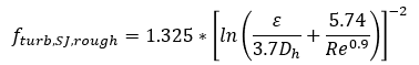
Colebrook-White Smooth/ Rough wall Friction
Coefficient![]()
For turbulent region Re > 4000
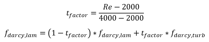
For laminar region Re < 2000
![]()
For transition region 2000 < Re < 4000
where
ε: is sand grain roughness
D: hydraulic diameter
Re: Reynolds Number
![]() are evaluated at the current Re number.
are evaluated at the current Re number.
Webb formulation![]()
Rather than a fixed turbulator friction factor, the user may choose to use the Webb formulation for a Turbulated wall Fanning friction factor as a function of Reynolds number:
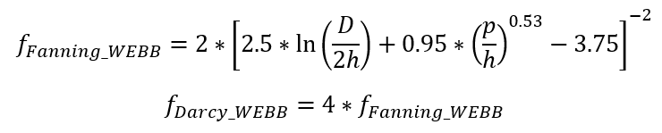
Where
h: the turbulator rib height (RIB_HEIGHT)
p: the turbulator rib pitch (RIB_PITCH)
For Fixed Friction Coefficient:
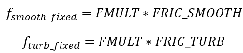
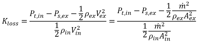
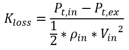
Kloss Calculation:
From these formulations, the friction Kloss can be calculated from
![]()
Where L is the Turbulator passage length. This friction Kloss is added to any user-specified Kloss to get total Kloss.
Flow Rate Calculations
|
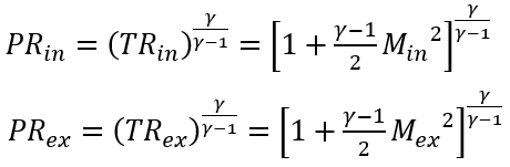
Nomenclature:
P = Pressure V = Velocity
A = Area PR = Pressure Ratio (Pt/Ps) TR = Temperature ratio (Tt/Ts)
Pt: Total pressure Ps: Static Pressure Tt: Total temperature |
Subscripts: in =inlet station ex =exit station |
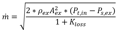
For Incompressible Liquid & Incompressible Fluid:
Solving the above equation for ![]() yields:
yields:
For a Compressible Gas:
For a compressible gas with incompressible K there is no analytic solution, so
![]() must be solved for numerically. A
residual is formulated for use in Newton’s method in order to calculate
must be solved for numerically. A
residual is formulated for use in Newton’s method in order to calculate ![]() for a compressible Kexpansion
type transition element. The residual is derived using the flow momentum
and continuity equations, and is expressed as:
for a compressible Kexpansion
type transition element. The residual is derived using the flow momentum
and continuity equations, and is expressed as:
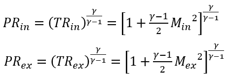
Based on the definition:
Where:
The Newton method drives Residual to zero by changing ![]() .
.
Exit Mach number is not a known quantity in FlowSimulator elements, but it can be calculated from known quantities using continuity:
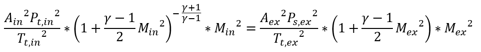
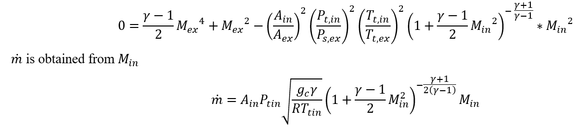
Which can be reduced to a quadratic equation for ![]() :
:
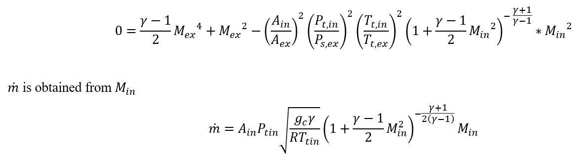
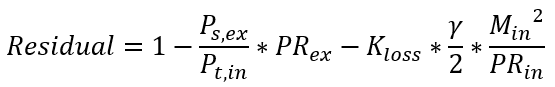
For a Fully Compressible Gas:
The Kloss formulation for a compressible gas with compressible K does
not yield an analytic solution for ![]() . A residual is formulated for use in
Newton’s method in order to calculate
. A residual is formulated for use in
Newton’s method in order to calculate ![]() for a compressible Kloss type
transition element. The residual is derived using the flow momentum and
continuity equations, and is expressed as:
for a compressible Kloss type
transition element. The residual is derived using the flow momentum and
continuity equations, and is expressed as:
![]()
Based on the definition:
![]()
Where:
Exit Mach number is not a known quantity in FlowSimulator elements, but it can be calculated from known quantities using continuity:
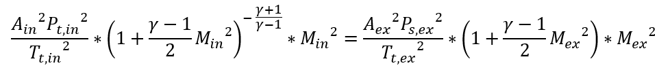
Which can be reduced to a quadratic equation for :![]()
Additional Momentum Loss
For Additional Momentum loss, Portion of Upstream Dynamic Head loss, Exit K Loss refer Solver General theory section.
Turbulator Element Outputs
Outputs in file with “res” extension. Output units controlled by user setting in “Output Control” panel.

|
Name |
Description | Units ENG, SI |
|---|---|---|
| CROSS-SECTION: | Shape of channel cross-section (CIRCULAR or ARBITRARY) | (None) |
| SMOOTH_FRIC: | How smooth/rough wall friction was calculated (OFF, FIXED, or SWAMEE) | (None) |
| TURB_FRIC: | How turbulator friction was calculated (OFF, FIXED, WEBB, or DP7505) | (None) |
| FLUID: |
Fluid compressibility option (INCOMPRESSIBLE, COMPRESSIBLE, or FULLY_COMPRESS) Fully compressible means the fluid is compressible and the K-relationship is compressible too. |
(None) |
| LENGTH | Length of passage | inch, m |
| ELEMENT_AREA | Cross-section area | inch2, m2 |
| HYD_DIAM | Hydraulic diameter | inch, m |
| ID | Inner diameter (shown if passage has annular cross-section) | inch, m |
| OD | Outer diameter (shown if passage has annular cross-section) | inch, m |
| ROUGHNESS | Roughness value (copy of input) | inch, m |
| SMOOTH_FMULT | Friction multiplier for smooth/rough wall friction (copy of input) | (unitless) |
| TURB_FMULT | Friction multiplier for turbulator friction (copy of input) | (unitless) |
| REYNOLDS_NUMBER | Calculated Reynolds number | (unitless) |
| SMOOTH_DARCY_FRIC | Friction coefficient for smooth/rough wall | (unitless) |
| TURB_DARCY_FRIC | Friction coefficient for turbulators | (unitless) |
| TOTAL_DARCY_FRIC | Total effective friction coefficient | (unitless) |
| K_LOSS_FRIC | Calculated K loss due to friction | (unitless) |
| K_LOSS_ADDIT | Additional user-specified K loss (copy of input) | (unitless) |
| K_LOSS_TOTAL | Total K loss (combination of friction and addition losses) | (unitless) |
| CD_RESULT | Result calculated from actual mass flow rate divided by ideal mass flow rate. The ideal mass flow rate assumes either K=0, Cp=Cp_ideal, or Effec=1. | (unitless) |
| FLUID_EXIT_THETA | Exit Theta angle of fluid after going through K-exit losses (only shows if there are K-exit losses) | deg |
| FLUID_EXIT_PHI | Exit Phi angle of fluid after going through K-exit losses (only shows if there are K-exit losses) | deg |
| PTS | Driving pressure relative to the rotational reference frame (i.e. rotor) at the transition inlet. | psia, MPa |
| PSIN |
Static pressure relative to the rotational reference frame (i.e. rotor) at the transition inlet. Limited by critical pressure ratio for supersonic flows when inlet area is smaller than exit area. |
psia, MPa |
| PTEX | Total pressure relative to the rotational reference frame (i.e. rotor) at the transition exit including supersonic effects. | psia, MPa |
| PSEX |
Static pressure relative to the rotational reference frame (i.e. rotor) at the transition exit. Limited by critical pressure ratio for supersonic flows. |
psia, MPa |
| PSEB | Effective sink (static) pressure downstream of the transition. | psia, MPa |
| TTS | Inlet Total temperature | deg F, deg K |
| TSIN | Inlet Static temperature | deg F, deg K |
| TTEX | Exit Total temperature | deg F, deg K |
| TSEX | Exit Static temperature | deg F, deg K |
| QIN |
Heat added Positive values indicate heat added to the fluid; negative values indicate heat removed. |
Btu/s, W |
| INVEL | Inlet Velocity | ft/s, m/s |
| INMN | Inlet Mach number | (unitless) |
| INREYN | Inlet Reynolds number | (unitless) |
| EXVEL | Exit Velocity | ft/s, m/s |
| EXMN | Exit Mach number | (unitless) |
| EXREYN | Exit Reynolds number | (unitless) |
References
- Blevins, R. D., Applied Fluid Dynamics Handbook, Krieger Publications, 2003
- Miller, D, Internal Flow Systems, Miller Innovations, 1990