FI CdComp Elements
FI CdComp General Description
The FI CdComp element is typically used to model flow through a circular hole in turbomachinery applications. This element is similar to a conventional orifice except that the Cd (Compressible Loss Coefficient) is calculated based on the geometry and flow. “CdComp” refers to the Cd being computed and “FI” is used to identify this element from a previous version of the CdComp element that is no longer recommended.
The Cd is calculated based on
- Reynolds Number of the flow through the hole
- Hole corner fillet or chamfer
- Orifice length over diameter (L/D)
- Ratio of Pressure upstream and downstream of the hole
- Pumping to account for hole angle and rotation
- Incidence Angle of the flow approaching the hole
- Difference between element and test upstream pressure
The calculation of the Cd is based on the method summarized in the paper by Idris et al. (ref 1.). A typical application would be for flow going through a hole in a compressor or turbine disk of a turbomachine. The incidence angle effect (#6 above) will account for the difference in the air and hole rotational speed. This element can be used for a wide range of applications where the circular hole Cd is not known. However, for an orifice plate in a nonrotating pipe user should consider the “Orifice Plate” element.
The element is typically used for compressible flow but Flow Simulator can use this element with incompressible or compressible fluid.
Quick Guide for CdComp Creation in the GUI
FI CdComp can be found under the “Compressible Gas Elements” or “Incompressible Liquid Elements” - “Orifices and Generic Losses” section


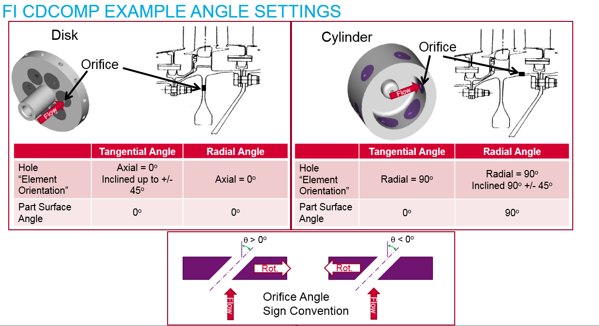
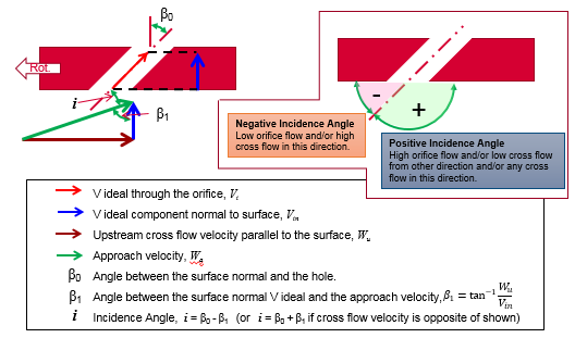
The correct “Part Surface Angle” and “Element Orientation” are critical for an accurate flow incidence angle. One thing to remember is that if the hole centerline is perpendicular to the part surface the “Part Surface Angle” and “Element Orientation” are the same. The “Part Surface Angle” and “Element Orientation” will only be different if the hole is at an angle to the part surface. Examples of “Part Surface Angle” and “Element Orientation” are shown below.
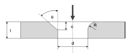
FI CDComp Inputs
Table of the inputs for the Cd comp element. See the image in the user interface to help understand geometric variables.
| FI CDComp Element Input Variables | ||
| Index | UI Name (.flo label) | Description |
| 1 | Area (AREA) | Orifice mechanical area. A diameter can also be entered in the UI and an area based on a circular hole will be calculated. |
| 2 |
Not in UI (K_INLET) |
Not used in solver |
| 3 |
Not in UI (EXIT_XFLOW) |
Not used in solver |
| 4 |
Not in UI (TAP_TYPE) |
Not used in solver |
| 5 |
Not in UI (ROUGHNESS) |
Not used in solver |
| 6 |
Corner Radius Or Chamfer Length (CORNER_R) |
Orifice inlet corner radius. When Corner Type (CORNTYP) is 3.0 (Chamfer), this field becomes the Orifice chamfer length (in) and is used in conjunction with the Chamfer Angle (CHAM_ANG) to describe the inlet geometry. |
| 7 | Length (LENGTH) | Orifice length |
| 8 | Hydraulic Diameter (HYD_DIA) | Orifice hydraulic diameter |
| 9,10 |
Not in UI (BETA_UP and _DN) |
Not used in solver |
| 11 | Element Inlet Orientation: Tangential Angle (THETA) |
Angle between the element centerline at the entrance of the element and the reference direction. If the element is rotating or directly connected to one or more rotating elements, the reference direction is defined as parallel to the engine centerline and the angle is the projected angle in the tangential direction. Otherwise, the reference direction is arbitrary but assumed to be the same as the reference direction for all other elements attached to the upstream chamber. Theta for an element downstream of a plenum chamber has no impact on the solution. |
| 12 | Element Inlet Orientation: Radial Angle (PHI) |
Angle between the element centerline at the entrance of the element and the THETA direction. (spherical coordinate system) Phi for an element downstream of a plenum chamber has no impact on the solution. |
|
13 14 15 |
Exit K Loss: Axial (K_EXIT_Z) Tangential (K_EXIT_U) Radial (K_EXIT_R) |
Head loss factors in the Z, U, and R directions based on the spherical coordinate system of theta and phi. Z theta and phi equal zero (the axial direction in a rotational field). U theta equals 90 and phi equals zero (the tangential direction in a rotational field). R theta equals zero and phi equal 90 zero (the radial direction in a rotational field). Valid values of K_EXIT_i (i = Z, U, R) range from zero (default) to one The three loss factors reduce the corresponding three components of velocity (idir) exiting the element
(Default value, 0.0, provides no loss) |
| 16 | Portion of UStrm Cham. Dyn. Head Lost (DQ_IN) |
Inlet dynamic head loss. Valid range is 0.0 to 1.0 inclusive. An entry outside this range will cause a warning message and the value used will be 0 or 1 (whichever value is closest to the entry). If DQ_IN > 0 and the upstream chamber has a positive component of relative velocity aligned with the centerline of the orifice, the driving pressure will be reduced by the equation:
(Default value = 0.) |
| 17 | Radius (RIN) |
Radius (in). Radial distance between the orifice inlet center and the engine centerline. (Do not use zero unless the orifice is not rotating) |
| 18 | Corner Type (CORNTYP) |
Orifice entrance corner type. 1.0: Sharp entrance (default) 2.0: Filleted entrance equation 3.0: Chamfered entrance equation CORNTYP=0.0 is corrected to CORNTYP=1.0 by both the Flow Simulator Solver and GUI. |
| 19 | Rotor Index (RPMSEL) |
Element rotational speed pointer. 0.0: Specifies a stationary element. 1.0: Points to general data ELERPM(1). 2.0: Points to general data ELERPM(2). 3.0: Points to general data ELERPM(3). -1.0: Element RPM is based on upstream fluid RPM. |
| 20 | Heat Input (QIN) |
Heat input QIN is heat added to (positive values) or removed from (negative) the fluid flowing through the orifice. In cases where multiple flow streams are modeled by a single element (i.e. NED and NLU not equal to 1), the value of QIN should be set to model the heat flow from only one of the restrictions. It may be used to simulate shaft work. (Links with YQIN in YEDAT common.) |
| 22 | Chamfer Angle (CHAM_ANG) |
Angle between corner chamfer and the hole centerline. Only used when CORNTYP=3.0. Default is 0.0. |
| 23 | Part Surface Angle: Tangential (THETA_SNORM) |
Part surface normal vector tangential angle (degrees). *Uses the same angle convention as the orifice itself. (Example: if the hole is drilled normal to the part surface the THETA_SNORM should be set equal to THETA) Default is 0.0. |
| 24 | Part Surface Angle: Radial (PHI_SNORM) | Part surface normal vector radial angle . |
| 25 |
Swirl Carryover (SWLCO) |
The amount of relative tangential velocity in the upstream chamber to carryover to the downstream chamber.
If |
| 26 |
Flow Equation Type (INCOMPR_FLG) |
Flag to specify flow compressibility for element calculations (Compressible vs. Incompressible). This is not actually used by the solver. The solver automatically changes equations based on the phase of the fluid entering the element. The element will use compressible equations for a gas and incompressible equations for a liquid. |


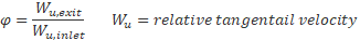
 , no swirl is carried over and
the air exits hole at wheel speed (swirl = 1), Swirl
carryover is near 0 for holes with any significant length
(L/D > 0.3)
, no swirl is carried over and
the air exits hole at wheel speed (swirl = 1), Swirl
carryover is near 0 for holes with any significant length
(L/D > 0.3) FI CdComp Theory
Flow Rate Calculation
The compressible flowrate is calculated using the following “flow function” equation (ref 5):
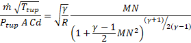
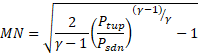
The mach number (MN) is related to the pressure ratio using
 (aka TTS)
 (aka PTS)
 (aka PSEB)

Other references (1,2) also have the flow function equation in different forms but they all represent the same thing.
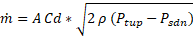
The incompressible flowrate is calculated using the following:
Cd Calculation
The calculation of the Cd is based on the method summarized in the paper by Idris et al. (ref 1.). The method steps though several characteristics of the orifice and the flow to calculate the final Cd. The details of each step are shown below.
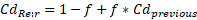
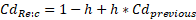
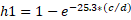
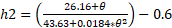
Reynolds Number Effect
The first step is the related to the hole Reynolds number (Re). The Reynolds number is based on the “ideal” velocity through the hole.
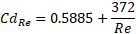
![]()
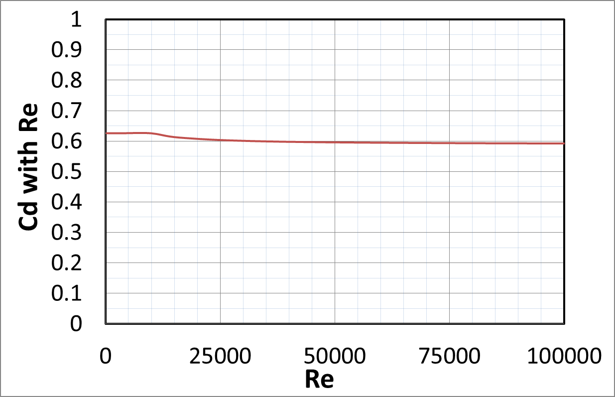
The Cd is not very sensitive to the Re. The minimum Re used in this equation is 10,000. The Cd used as the basis for the next step is always around 0.6
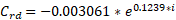
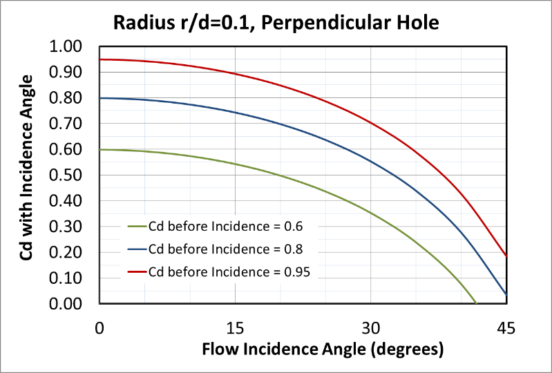
Hole Corner Fillet or Chamfer
A fillet or chamfer can significantly reduce the losses in the hole (a higher Cd).
For a hole with a circular fillet (ref 1):


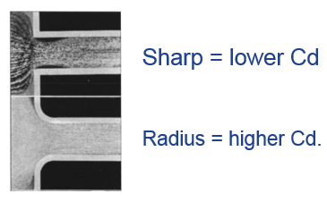
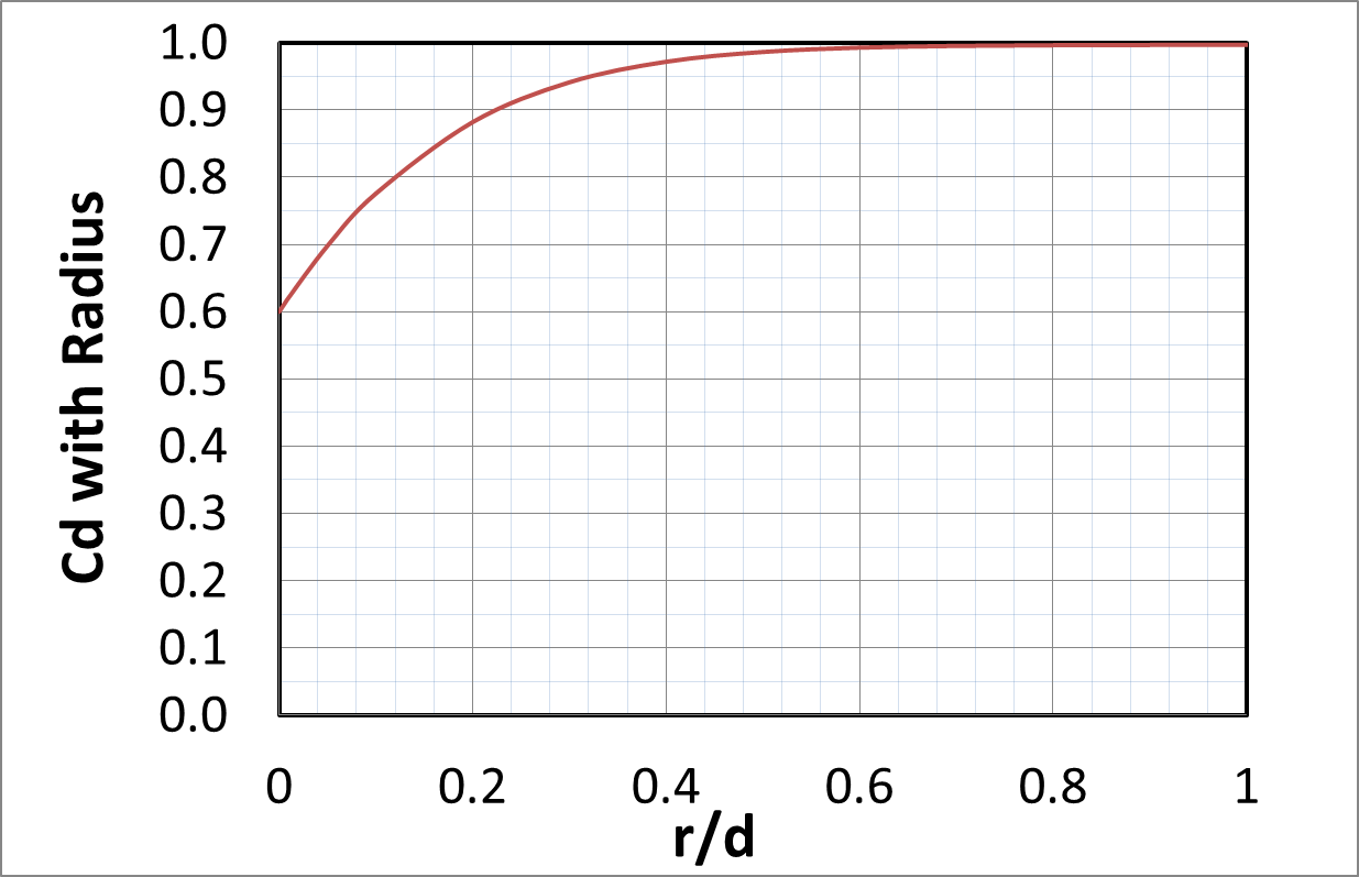
The example shows streamlines entering a hole with a sharp corner and a hole with a large fillet. The hole with a sharp corner shows flow separation while the hole with a radius does not. The plot demonstrates the radius effect and may not represent the final Cd.
For a hole with a chamfer (ref 1):
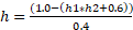


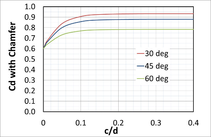
The plot demonstrates the radius effect and may not represent the final Cd.
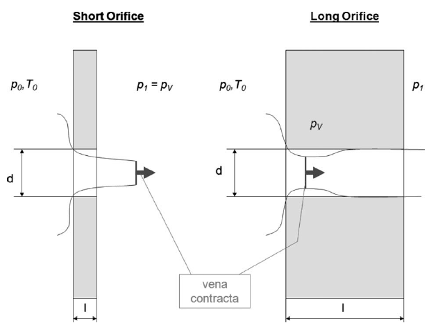
Orifice Length over Diameter (L/D)
The length of the orifice affects the reattachment of the orifice flow. If the flow can reattach inside the orifice length the losses can be reduced (Cd increased). The program adjusts the length due to a fillet or chamfer so the user should enter the orifice length as if there was no fillet or chamfer. The program does not adjust the length for the hole angle. The user should enter a hole length that includes the angle effect. Equation taken from ref 2.
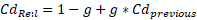


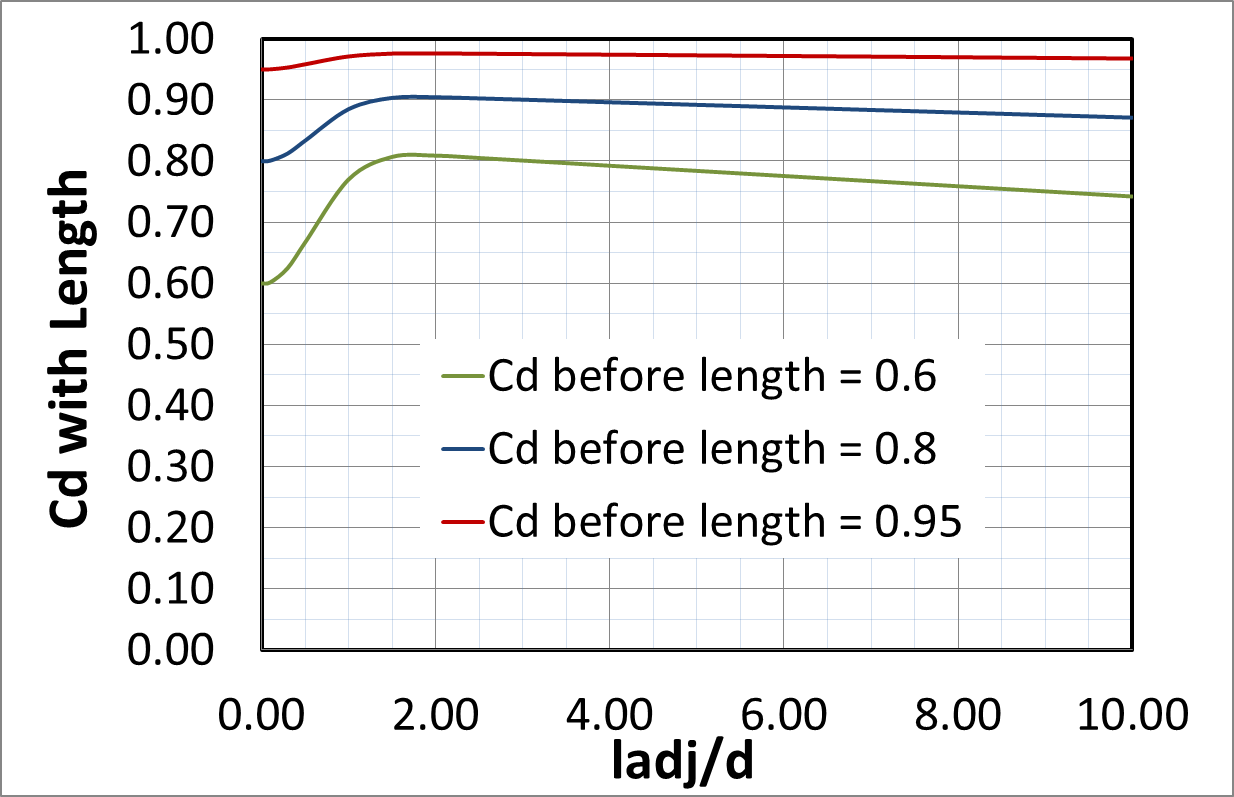
The plot demonstrates the length effect and may not represent the final Cd. Note that the maximum Cd occurs between L/D = 1.5 and 2. Friction losses increase as the orifice gets longer so Cd decreases for L/D > 2
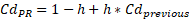
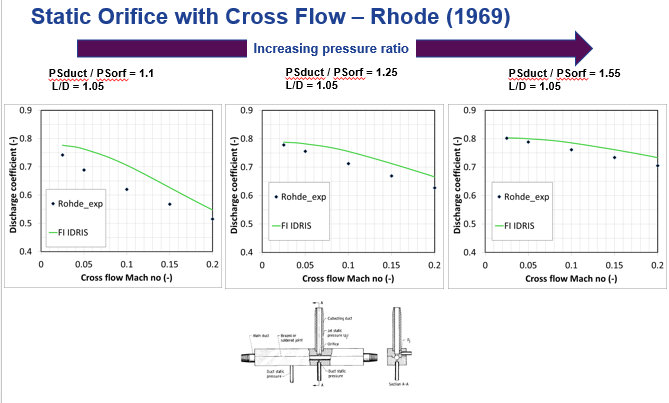
Ratio of Pressure Upstream and Downstream of the Hole
The pressure ratio effect accounts for the compressibility of the gas. It will have no affect for liquid (incompressible) fluids. The maximum pressure ratio used in this equation is 5.0. As the pressure ratio increases the vena contracta increases to cause the higher Cd. Equation taken from ref 1.


The plot demonstrates the pressure ratio effect and may not represent the final Cd. Note that the Cd increases after the choking pressure ratio (~1.9). So, the orifice flowrate may increase after the PR exceeds the choking PR.
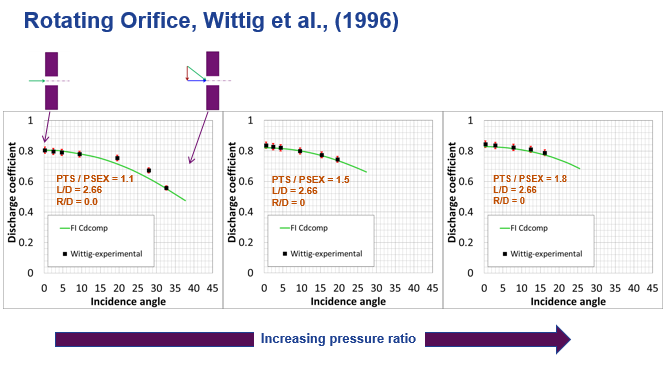
Pumping to Account for Hole Angle and Rotation
Idris (ref 1) describes a pumping effect that accounts for the fact that the Cd for Incidence angle = 0o is higher for a rotating hole (which must be angled to achieve zero incidence) that it is for a stationary hole. The physics behind this are not clear. The effect is included to match the Idris data.
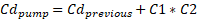


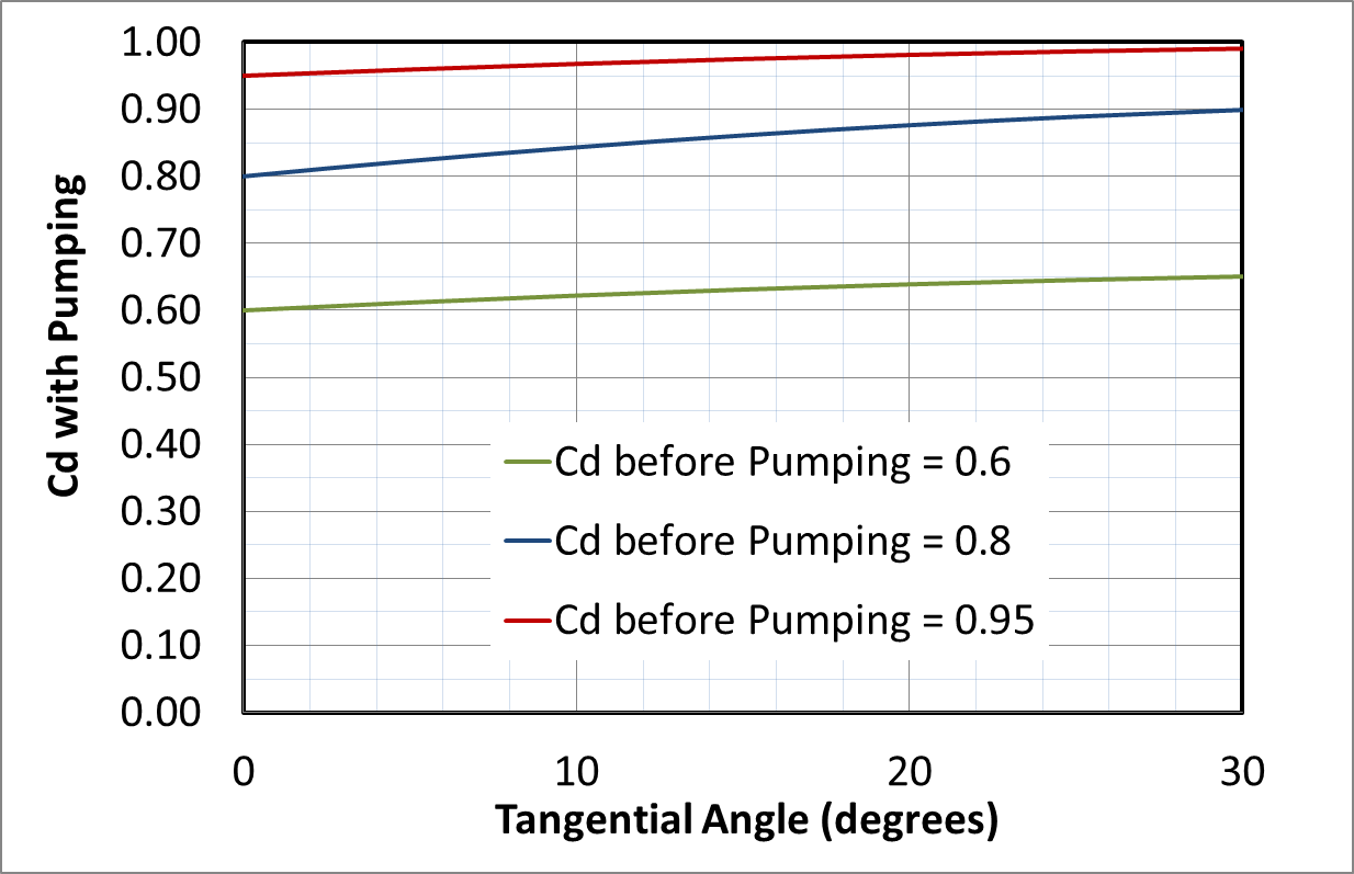
The plot demonstrates the pumping effect and may not represent the final Cd.
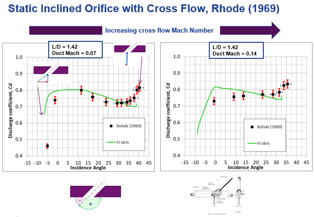
Incidence Angle of the Flow Approaching the Hole
The final Cd is very sensitive to the incidence angle effect. If the upstream flow approaches a hole at a steep angle a large separation region can fill a significant portion of the hole. This will decrease the Cd and flowrate. The incidence angle affects are taken from ref 1. The hole corner treatment and the angle of the hole influence the incidence angle effect.
For holes that are perpendicular to the part surface:
For a hole with a sharp corner:
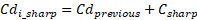
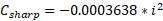


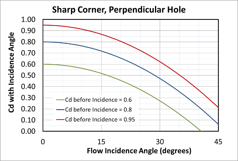
The plot demonstrates the incidence effect and may not represent the final Cd. The absolute value of the incidence angle is used in this equation. The maximum incidence angle allowed is 45o.
For a hole with a circular fillet:
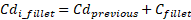


The plot demonstrates the incidence effect and may not represent the final Cd. The absolute value of the incidence angle is used in this equation. The maximum incidence angle allowed is 45o. The maximum r/d allowed is 0.25 .
For a hole with a chamfer:


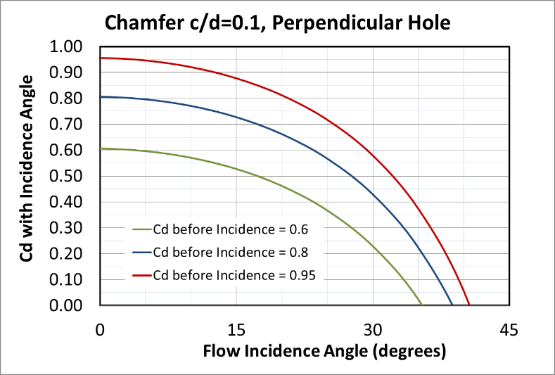
The plot demonstrates the incidence effect and may not represent the final Cd. The absolute value of the incidence angle is used in this equation. The maximum incidence angle allowed is 30o. The maximum c/d allowed is 0.20.
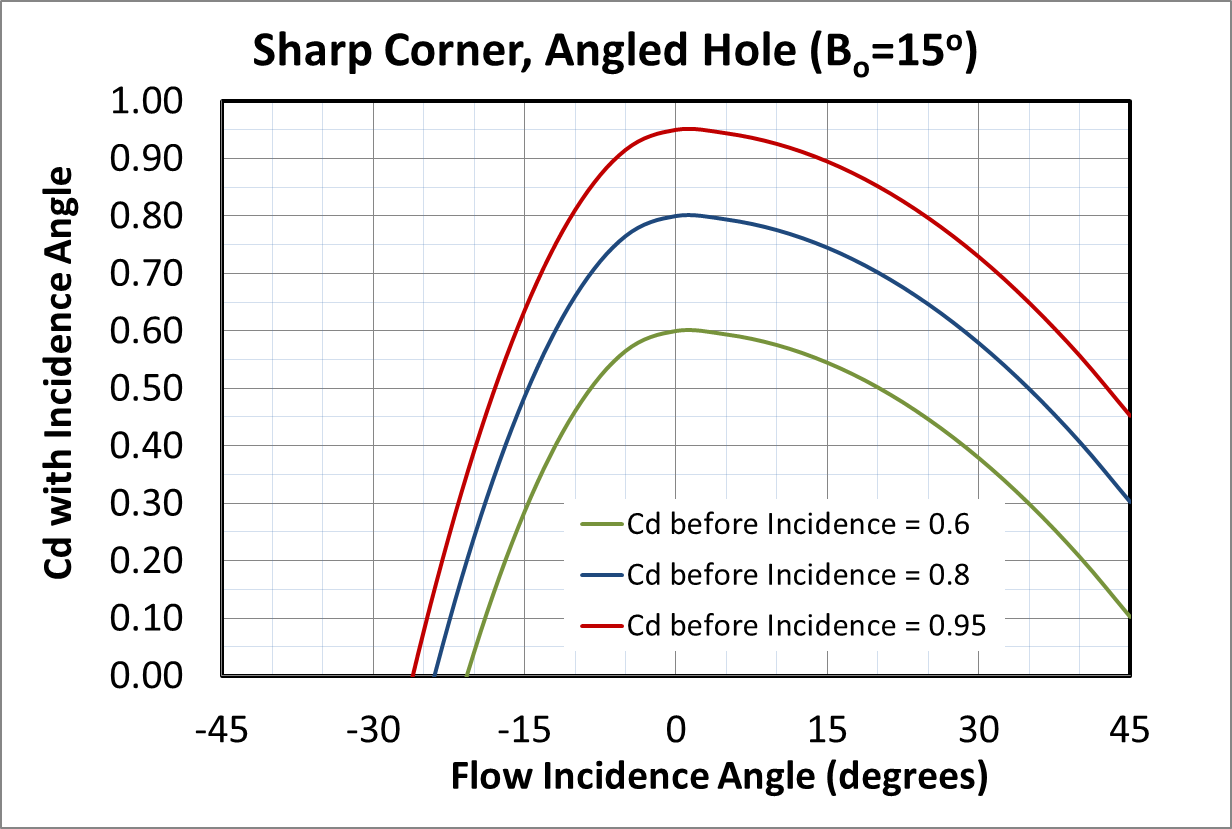
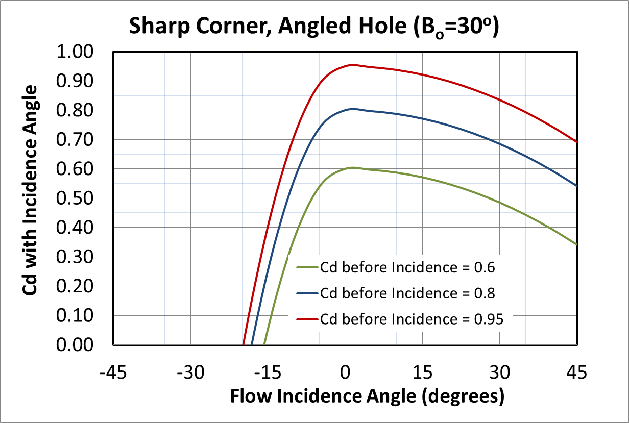
For holes that are angled to the part surface:
There is no data available for the incidence angle effect on an angled hole with a fillet or chamfer. The sharp corner Cd will be used even if the hole has a fillet or chamfer. The effect is different for holes with positive and negative incidence.
For a hole with a sharp corner (Positive incidence) :


For a hole with a sharp corner (Negative incidence) :

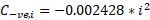

The following plots show the effect of incidence angle on holes that have a 15o, 30o, and 45o angle with the part surface. The plots demonstrate the incidence effect and may not represent the final Cd.
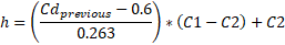
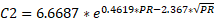
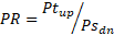
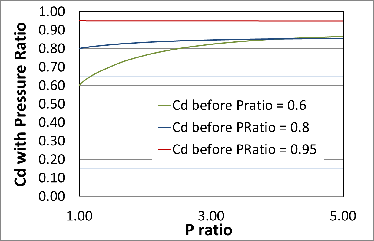
Difference between Element and Test Upstream Pressure
The final effect is not from the Idris paper and is specific to Flow Simulator. The empirical based Cd equations and Flow Simulator may use different upstream pressures (Ptup, aka PTS) in the flow function calculation. The test typically used a total pressure based on the relative velocity but Flow Simulator typically uses a pressure less than this total pressure. The pressure that Flow Simulator uses is based on the upstream chamber velocity vector that is aligned with the centerline of the hole, and the entrance loss setting (Portion of Ustrm Cham. Dyn. Head Lost).


FI CDComp Outputs

Outputs in file with “res” extension. Output units controlled by user setting in “Output Control” panel.
| Name | Description | Units ENG, SI |
|---|---|---|
| ELEMENT_AREA |
Cross-sectional area. (Usually an echo of the user input unless modified inside Flow Simulator.) |
inch2, m2 |
| CD |
Final discharge coefficient. Calculated in a multi-step process in the CDCOMP routine. |
(unitless) |
| R |
Inlet corner radius. (Usually an echo of the CORNER_R input unless modified inside Flow Simulator). |
Inch, mm |
| L |
Length. (Usually an echo of the LENGTH input unless modified inside Flow Simulator). |
Inch, mm |
| D |
Hydraulic diameter. (Usually an echo of the HYD_DIA input unless modified inside Flow Simulator). |
Inch, mm |
| RPM | Rotational speed of the restriction | rev/min |
| RIN |
Radius to the orifice inlet from the engine centerline. (Usually an echo of the RIN input unless modified inside Flow Simulator). |
Inch, m |
| THETA_SNORM | Part surface normal vector tangential angle | degrees |
| PHI_SNORM | Part surface normal vector radial angle (degrees). | degrees |
| PTS | Driving pressure relative to the rotational reference frame (i.e. rotor) at the restriction inlet. | Psia, MPa |
| PTEX | Total pressure relative to the rotational reference frame (i.e. rotor) at the restriction exit including supersonic effects. | Psia, MPa |
| PSEX |
Static pressure relative to the rotational reference frame (i.e. rotor) at the restriction exit. Limited by critical pressure ratio for supersonic flows. |
Psia, MPa |
| PSEB | Effective sink (static) pressure downstream of the restriction. | Psia, MPa |
| TTS | Total relative temperature of fluid entering the element | deg F, deg K |
| VCMN | Fluid Mach number relative to the rotational reference frame (i.e. rotor) at the vena contracta. | (unitless) |
| VXA | Fluid velocity relative to the rotational reference frame (i.e. rotor) at the restriction exit before heat input (QIN) effects. | ft/s, m/s |
| EXMN | Fluid Mach number relative to the rotational reference frame (i.e. rotor) at the restriction exit before heat input (QIN) effects. | (unitless) |
| QIN |
Heat input. Positive values indicate heat added to the fluid; negative values indicate heat removed. |
BTU/s, W |
| DT | Change in total temperature relative to the rotational reference frame (i.e. rotor) due to heat input (QIN). | deg F, deg K |
| TEX | Total temperature relative to the rotational reference frame (i.e. rotor) at the restriction exit. | deg F, deg K |
| VEX | Fluid velocity relative to the rotational reference frame (i.e. rotor) at the restriction exit including heat input (QIN) effects. | ft/sec, m/s |
| CDRE | Incompressible discharge coefficient based on the fluid Reynolds number. | (unitless) |
| CDR | Incompressible discharge coefficient (CDRE) adjusted for inlet corner radius effects. | (unitless) |
| CDRL | Incompressible discharge coefficient (CDR) adjusted for effects of length or thickness. | (unitless) |
| CDRL_PR | Incompressible discharge coefficient (CDRL) adjusted for compressibility effects. | (unitless) |
| CDRL_PR_PUMP | Compressible discharge coefficient (CDRL_PR) adjusted for hole angle and rotation. | (unitless) |
| CDRLU | Compressible discharge coefficient (CDRL_PR_PUMP) adjusted for effects of fluid rotational speed relative to the rotational reference frame (i.e. rotor) at the restriction inlet. | (unitless) |
| CD | Compressible discharge coefficient (CDRLU) adjusted for effects of source pressure difference between empirical equations and Flow Simulator PTS. Same as the “Final Discharge Coefficient” already listed in the element output. | (unitless) |
| V_IDEAL | Ideal velocity in the hole. (Use Cd=1 and Ptrel as the upstream pressure) | ft/sec, m/s |
| SPARV_UP | Total magnitude of hole upstream velocity parallel to the part surface. | ft/sec, m/s |
| SPARV_Z | Axial component of hole upstream velocity parallel to the part surface. | ft/sec, m/s |
| SPARV_R | Radial component of hole upstream velocity parallel to the part surface. | ft/sec, m/s |
| SPARV_U | Relative tangential component of hole upstream velocity parallel to the part surface. | ft/sec, m/s |
| SWLCO | Swirl Carryover through the hole | (unitless) |
| XK_INLET | Swirl Ratio upstream of the hole. | (unitless) |
| RPM_REF_IN | Reference RPM for the swirl ratio upstream of the hole. | rev/min |
| XK_EXIT | Swirl Ratio downstream of the hole. | (unitless) |
| RPM_REF_EX | Reference RPM for the swirl ratio downstream of the hole. | rev/min |
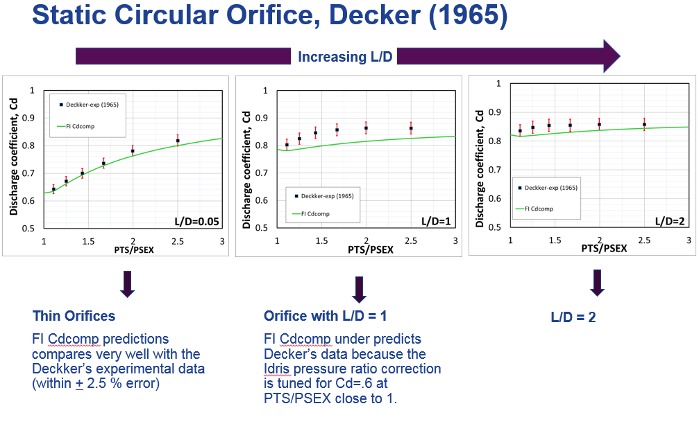
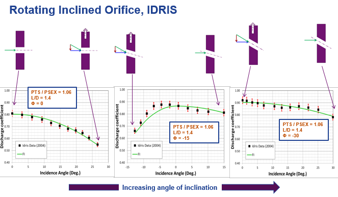
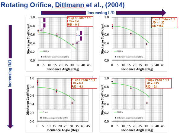
FI CDComp Validation
The FI CDComp results were compared to Cd and flow results from various tests as shown below.
CDComp References
- A. Idris, K. R. Pullen, “Correlations for the discharge coefficient of rotating orifices based on the incidence angle”, Proceedings of IMechE, Part A: J. Power and Energy, Vol-219, Year-2005
- Marcus Hüning, “Comparison of Discharge Coefficient Measurements and Correlations for Orifices with Cross-Flow and Rotation”, Journal of Turbo machinery, Vol-132, p031017-1-10, Year-2010.
- A. Alexiou, N.J. Hills, C.A. Long, A.B. Turner, L.-S. Wong, J.A. Millward, “Discharge coefficients for flow through holes normal to a rotating shaft”, International Journal of Heat and Fluid Flow, Vol-21, p701-709, Year-2000.
- W. F. McGreehan, M. J. Schotsch, “Flow Characteristics of Long Orifices With Rotation and Corner Radiusing”, Journal of Turbo machinery, Vol-110, p213-217, Year-1988
- Miller, D.S., “Internal Flow Systems,” Miller Innovations, 2nd Edition, 1990
- Rhode, J. E., Richards, H. T., Metger, G. W., Discharge Coefficients for Thick Plate Orifices With Approach Flow Perpendicular and Inclined to the Orifice Axis, 1969, Technical Report, NASA-TN-D-5467
- Dittmann, M., Dullenkopf, K., Witting, S., Discharge coefficients of rotating short orifices with radiused and chamfered inlets, J. Turbomach.,2004, 126, 803-808.
- Wittig, S., Kim, S., Jakoby, R., WeiBert, I., Experimental and Numerical Study of Orifice Discharge Coefficients in High-Speed Rotating Disks, Transactions of the ASME, 1996, 118, 400-407