Combination Flow Elements
Combination Flow Element General Description
The Combination Flow Element is like Fixed Flow Element which is used to supply a constant flow rate by combining the Flow fractions from different elements/components. In this type the % of flow from each entry of flow elements/components is added together to get a total flow amount for the element. Flow is assumed to leave the element at the temperature specified for the upstream chamber. The momentum can be transferred downstream by providing the Exit area, angles, and rotation inputs.
Quick Guide for Combination Flow Element Creation in the GUI

Combination Flow Elements are available under both Compressible Gas Elements & Incompressible Liquid Elements sections. Users can use maximum of 20 Flow element combinations & its fractions to calculate the flow through combination flow element. There are options provided to sum only positive or negative flows. Users can decide whether to include this element as part mass balance across the circuit. If the mass balance is excluded, then combo-flow element act as a ghost element and is omitted from the flow network solution.
Combination Flow Element Inputs
Table of the inputs for the Combination Flow Element.
| Element Specific Combination Flow Element Input Variables | ||
| Index | UI Name (. flo label) | Description |
| 1 | Subtype (SUB_TYPE) |
Element subtype. (NOT CURRENTLY USED) 1.0: No Meaning (Default value = 1.) |
| 2 | Number of Flows (NUMFLO) | Number of Flow Elements used in the combination flow up to a maximum of 20. |
| 3 | Area (AREA) | Physical area used to calculate exit velocity (Optional input). |
| 4 | Element Inlet Orientation: Tangential Angle (THETA) |
Angle between the element centerline at the entrance of the element and the reference direction.
If the element is rotating or directly connected to one or more rotating elements, the reference direction is defined as parallel to the engine centerline and the angle is the projected angle in the tangential direction. Otherwise, the reference direction is arbitrary but assumed to be the same as the reference direction for all other elements attached to the upstream chamber.
Element exit orientation for the theta angle is the same in the inlet THETA for fixed flow element types. |
| 5 | Element Inlet Orientation: Radial Angle (PHI) |
Angle between the element centerline at the entrance of the element and the THETA direction. (spherical coordinate system)
Element exit orientation for the phi angle is the same in the inlet PHI for fixed flow element types. |
| 6 | Rotor Index (RPMSEL) |
Reference rotor index for user-supplied swirl. Stationary (Database Value = 0.0) Rotor 1 (Database Value = 1.0): Points to general data Shaft 1 Rotor Speed. Rotor 2 (Database Value = 2.0): Points to general data Shaft 2 Rotor Speed Rotor 3 (Database Value = 3.0): Points to general data Shaft 3 Rotor Speed Rotates with Air (database Value = -1.0): Element RPM is based on upstream fluid RPM |
| 7 | Radius (RADIUS) |
Radius. Radial distance between the combination flow and the engine centerline. (Do not use zero unless the fixed flow is not rotating) |
| 8 | Mass Balance Input (MASS_BAL) | Flag to specify whether FlowSimulator solver includes the element in the mass balance. |
| 9 | Flow Fractions: Element ID (FLOW_ELEMENTS) | Array of up to 20 values storing Element numbers for use in the combination flow. |
| 10 | Flow Fractions: Fraction (FLOW_FRACTION) |
Array of up to 20 values storing flow fractions of the flows corresponding to the same entries in the FLOW_ELEMENTS array.
|
| 11 | Summation Type (SUM_TYPE) |
Type of sum to perform (all, just positive, or just negative) SUM_ALL = 0 SUM_POS = 1 SUM_NEG = 2 |
Combination Flow Element Theory
Flow Rate through combination element is the summation of Flow Fractions from the different flow elements selected as shown below.
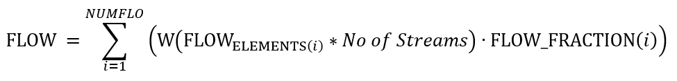
If Exit Area is greater than 0, then
For Incompressible flow:
![]()
For Compressible Flow:
XMBX = Total pressure flow parameter
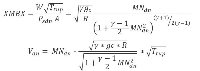
| Nomenclature: | Subscripts: |
| W: Mass flow rate | up: Upstream station |
| Tt: Total Temperature | dn: Downstream station |
| Pt: Total pressure | ref: Reference |
| Ps: Static pressure | |
| R: Gas Constant | |
| MN: Vena Contracta Mach Number | |
| gc: Gravitational Constant |
Combination Flow Element Outputs
The following listing provides details about combination flow element output variables.
| Name | Description | Units |
|---|---|---|
| ELEMENT_AREA |
Cross-sectional area. (An echo of the user input.) |
inch2, m2 |
| ELEM | Column of Element numbers used in the combination flow element summing. | (N/A) |
| ELEMENT FLOW | Column of flow values associated with the Element numbers of the same row. | Lbm/s, Kg/s |
| FRACTION | Column of fractions of the flow values of the same row used in summing the total combination flow. | (fraction) |
| MIXED FLOW | Column of the amount of flow pulled from the Element numbers of the same row. | Lbm/s, Kg/s |
| TOTAL | Total summed flow from all sources of Elements in the combination flow. | Lbm/s, Kg/s |