Transition Elements
Transition Element General Description
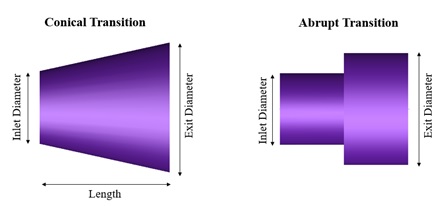
There are two Flow Simulator transition elements available. Both can be used in compressible flow and incompressible flow simulations. This element is used to model various types of expansions (Ex: Flow through diffuser, Flow through an abrupt expansion) and contractions (Ex: Flow through reducers, Flow through a sudden contraction). These include abrupt and conical shaped as well as parameter inputs for defining the behavior of arbitrary shaped expansions and contractions.
Quick Guide for Transition Element Creation in the GUI
Both Conical & Abrupt Transitions can be found under both “Compressible Gas Elements” & “Incompressible Liquid Elements” - “Expansions & Contraction” section

The geometric inputs like inlet diameter, exit diameter and length are mandatory inputs. Apart from these, inputs related to friction are required if friction options are selected. Descriptions about each input is described below in “Transition Element Inputs” section.
Transition Element Inputs
Table of the inputs specific for the Conical Transition Element.
| Conical Transition Element Input Variables | ||
| Index | UI Name (. flo label) | Description |
| 1 | Expansion Type (EXPAN_TYPE) |
Type of expansion. 10:Expansion with Fixed K Loss. 30: Conical Expansion – Blevins 31: Conical Expansion – Miller 40: Expansion with Fixed Cp (Static Pressure Recovery Coefficient) 50: Expansion with Fixed Effectiveness 60: CD Loss |
| 2 | Contraction Type (CONTRAC_TYPE) |
Type of contraction. 70:Contraction with Fixed K Loss. 90: Conical Contraction – Blevins 91: Conical Contraction - Miller |
| 3 | Expansion Parameter (K_EXPAN) |
If EXPAN_TYPE=10, then K_EXPAN is an expansion K loss (Total Pressure Loss Coefficient). If EXPAN_TYPE=40, then K_EXPAN is a diffuser Cp If EXPAN_TYPE=50, then K_EXPAN is a diffuser Effectiveness If EXPAN_TYPE=60, then K_EXPAN is the CD Loss Parameter. For other expansion types, the expansion parameter is determined by equations or table lookups, so this input is not required. |
| 4 | Contraction Parameter (K_CONTRAC) |
If CONTRAC_TYPE=70, then K_CONTRAC is a contraction K loss For other contraction types, the contraction parameter is determined by equation or table lookups, so this input is not required. |
| 5 | Length (LENGTH) | Length is used for calculation of the expansion/contraction angle of the conical types and is used in the additional friction calculation. |
| 6 | Turbulent Friction Relation (FRIC_MODE) |
Friction options 0: Friction Off 1: Friction calculated with Swamee-Jain approximation to Colebrook-White (Moody Diagram) 2: Friction specified by user in the FRICTION field. |
| 7 | Darcy Friction Coefficient (FRICTION) | When FRIC_MODE=2 (User-specified friction), Darcy Friction Coefficient should be provided. |
| 8 | Roughness (ROUGHNESS) |
Roughness value When FRIC_MODE=1 (friction calculated with Swamee-Jain approximation to Colebrook-White), roughness can be provided. Sand-grain roughness is the default type, since that is what Moody, Colebrook-White, Swamee, etc. are based on. |
| 9 | Friction Multiplier (FMULT) | A user-specified multiplier for friction. This should only be used with calculated friction values. FMULTs are often used to account for roughness effects, so FMULT should probably be used only when ROUGHNESS =0. |
| 10 | Roughness Type (ROUGH_TYPE) |
This tells what type of rough the ROUGHNESS value is. 0: Sand-Grain Roughness 1: Average-Absolute Roughness 2: Root-Mean-Square Roughness 3: Peak-to-Valley Roughness |
Table of the inputs specific for the Abrupt Transition Element.
| Abrupt Transition Element Input Variables | ||
| Index | UI Name (. flo label) | Description |
| 1 | Expansion Type (EXPAN_TYPE) |
Type of expansion. 10:Expansion with Fixed K Loss. 20: Abrupt Expansion – Simple 22: Abrupt Expansion – Miller |
| 2 | Contraction Type (CONTRAC_TYPE) |
Type of contraction. 70:Contraction with Fixed K Loss. 80: Abrupt Contraction – Simple 81: Abrupt Contraction – Polynomial 82: Abrupt Contraction – Miller1 83: Abrupt Contraction – Miller2 |
| 3 | Expansion Parameter (K_EXPAN) |
If EXPAN_TYPE=10, then K_EXPAN is an expansion K loss (Total Pressure Loss Coefficient). For other expansion types, the expansion parameter is determined by equations or table lookups, so this input is not required. |
| 4 | Contraction Parameter (K_CONTRAC) |
If CONTRAC_TYPE=70, then K_CONTRAC is a contraction K loss For other contraction types, the contraction parameter is determined by equation or table lookups, so this input is not required. |
| 5 | Minor Fillet Radius (FRAD_MINOR) | Fillet Radius at the smaller diameter location |
Table of the common inputs for both Conical & Abrupt Transition Element.
| Transition Element Common Input Variables | ||
| Index | UI Name (. flo label) | Description |
| 1 | Cross-Section Shape (CS_MODE) |
Cross-section shape allows user to specify geometry in three different ways. 1: Circular with Inlet and Exit Area specified (Internally, the solver computes diameters and perimeters.) 2: Circular with Inlet and Exit Diameter specified (Internally, the solver computes areas and perimeters) 3: Arbitrary Shape with Inlet and Exit Area as well as Inlet and Exit Hydraulic Diameter specified. (Internally, the solver computes the perimeters.) |
| 2 | Inlet Area (INLET_AREA) |
Area at transition inlet If INLET_AREA is greater than EXIT_AREA, then the transition is understood to be a contraction when flow is in the forward direction (from the user-defined upstream chamber to the user-defined downstream chamber). If the flow direction is reversed in the final solution, the transition element treats the channel as an expansion (using the EXPAN_TYPE input, etc.). |
| 3 | Exit Area (EXIT_AREA) |
Area at transition exit If EXIT_AREA is greater than INLET_AREA, then the transition is understood to be an expansion when flow is in the forward direction (from the user-defined upstream chamber to the user-defined downstream chamber). If the flow direction is reversed in the final solution, the transition element treats the channel as a contraction (using the CONTRAC_TYPE input, etc.). |
| 4 | Inlet Hydraulic Diameter (INLET_DH) |
Diameter (or Hydraulic Diameter) at transition inlet Same flow direction logic as explained in the INLET_AREA section |
| 5 | Exit Hydraulic Diameter (EXIT_DH) |
Diameter (or Hydraulic Diameter) at transition exit Same flow direction logic as explained in the EXIT_AREA section |
| 6 | Portion of Ustrm Chamb. Dyn. Head Lost (DQ_IN) | Inlet dynamic head loss. Refer General solver theory sections for more details about this input |
| 7 | Element Inlet Orientation: Tangential Angle (THETA) |
Angle between the element centerline at the entrance of the element and the reference direction. If the element is rotating or directly connected to one or more rotating elements, the reference direction is defined as parallel to the engine centerline and the angle is the projected angle in the tangential direction. Otherwise, the reference direction is arbitrary but assumed to be the same as the reference direction for all other elements attached to the upstream chamber. THETA for an element downstream of a plenum chamber has no impact on the solution except to set the default value of THETA_EX. (See also THETA_EX) |
| 8 | Element Inlet Orientation: Radial Angle (PHI) |
Angle between the element centerline at the entrance of the element and the THETA direction. (spherical coordinate system) PHI for an element downstream of a plenum chamber has no impact on the solution except to set the default value of PHI_EX. (See also PHI_EX) |
| 9 |
Exit K Loss: Axial (K_EXIT_Z) Tangential (K_EXIT_U) Radial (K_EXIT_R) |
Head loss factors in the Z, U, and R directions based on the spherical coordinate system of theta and phi. (Default value provides no loss). Refer General solver theory sections for more details about this input |
| 10 | Element Exit Orientation: Tangential Angle (THETA_EX) |
Angle between the orifice exit centerline and the reference direction. THETA_EX is an optional variable to be used if the orientation of the element exit differs from that of the element inlet. The default value (THETA_EX = -999) will result in the assumption that THETA_EX = THETA. Other values will be interpreted in the manner presented in the description of THETA. |
| 11 | Element Exit Orientation: Radial Angle (PHI_EX) |
Angle between the orifice exit centerline and the THETA_EX direction. PHI_EX is an optional variable to be used if the orientation of the element exit differs from that of the element inlet. The default (PHI_EX = -999) will result in the assumption that PHI_EX = PHI. Other values will be interpreted in the manner presented in the description of PHI. |
| 12 | Heat Addition Mode (HEAT_MODE) |
This tells the solver how to interpret QIN. 0: Adiabatic 1: Heat addition 2: Head addition proportional to element mass flow rate 3: Delta Total temperature 4: Fixed Fluid Total temperature at exit |
| 13 | Heat Added (QIN) |
Heat Added – if Heat Mode =1 or 2 Delta.T – if Heat Mode =3 Fixed total temperature at exit = 4 |
| 14 | Fluid Compressibility Mode (FLUID_MODE) |
The user can choose which solution algorithm to use. 1: Compressible Fluid 2: Incompressible Fluid 3: Compressible with Compressible K 4: Incompressible liquid |
| 15 |
Reynolds Number Correction Relation for K (RE_CORR) |
The user can choose which to adjust K (or Cp) based according to the following options. 0: Off 1: General Purpose – Recommended for abrupt expansion, abrupt contraction, and valves 2: Diffuser correction & Conical Expansion – Recommended for diffusers Refer General solver theory sections for more details about this input |
Transition Element Theory
The transition element module applies conservation of mass, momentum, and energy equations to relate static pressure, total pressure, total temperature, and flow rate at the element inlet with those at the element exit. All contractions are governed by contraction Kloss for their momentum equation. Expansion elements are divided into two categories: Those that use expansion K and those that use diffuser CP for the momentum equation. All transitions break down into these three different momentum equation types. In addition, transitions use one of three different gas assumptions:
- Incompressible relation between Pt and Ps, and incompressible K definition
- Compressible relation between Pt and Ps, and incompressible K definition. (Recommended for general usage)
- Compressible relation between Pt and Ps, and compressible K definition. (Recommended only if K is defined compressible)
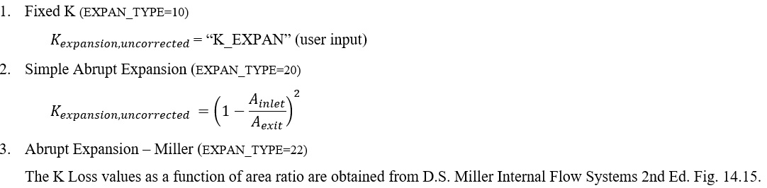
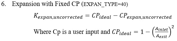
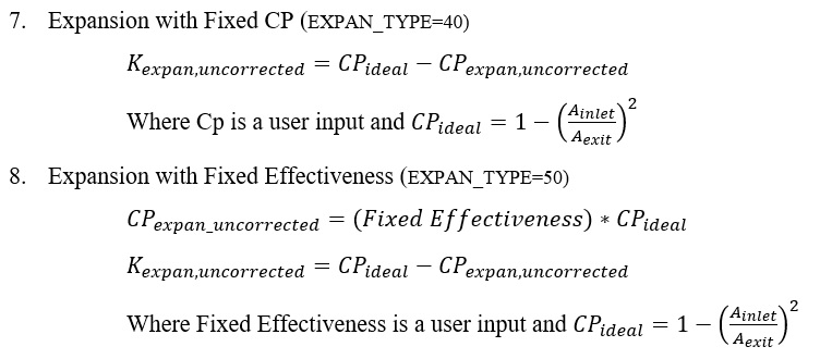
Expansion – Kloss Calculations
Expansion K is calculated differently based on the “Expansion Type” selected for the transition element. The K formulations for the different expansion types are outlined below.


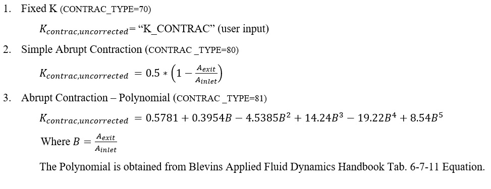
Contraction – Kloss Calculations
Contraction K is calculated differently based on the “Contraction Type” selected for the transition element. The K formulations for the different expansion types are outlined below.


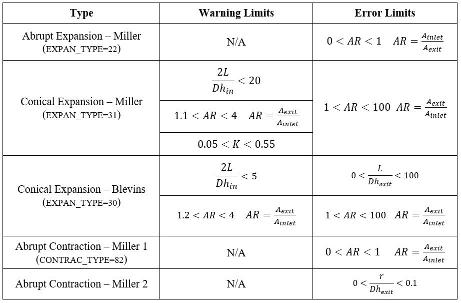
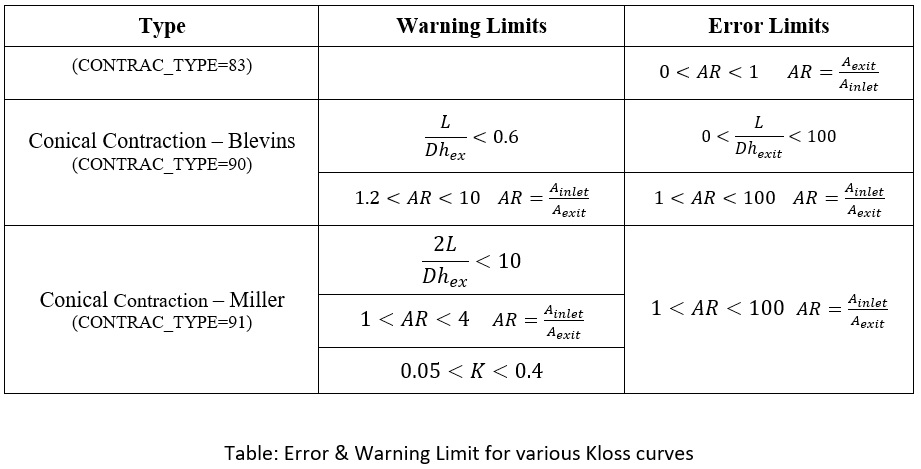
Kloss ( ) as calculated using the above formulations will be
corrected if opted to account for Reynolds numbers using one of the options
mentioned below. The details of correction factors are available under General solver theory
sections
) as calculated using the above formulations will be
corrected if opted to account for Reynolds numbers using one of the options
mentioned below. The details of correction factors are available under General solver theory
sections
- General Purpose – Recommended for abrupt expansion, abrupt contraction, and valves (RE_CORR = 1)
- Diffuser correction & Conical Expansion – Recommended for diffusers (RE_CORR = 2)
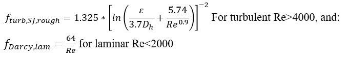
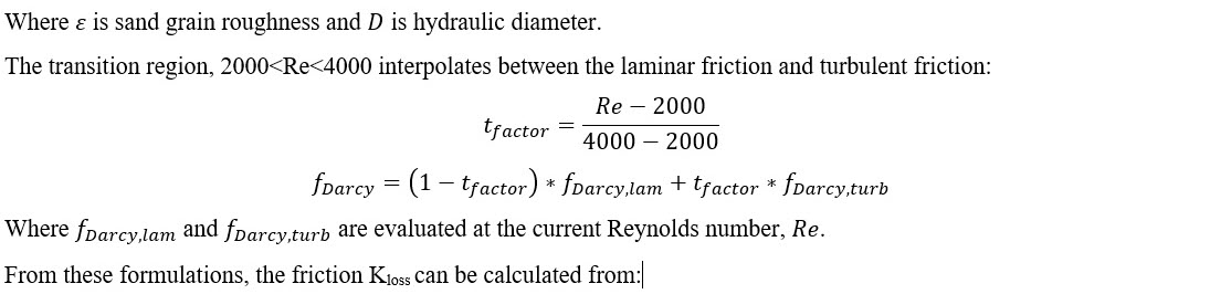
Friction Loss Calculations
The transition element currently supports friction coefficients for walls with specified surface roughness. There are two friction options:
- User-specified friction factor
- Swamee-Jain approximation of the Colebrook-White equation (Moody diagram) for wall Darcy friction factor as a function of Reynolds number:
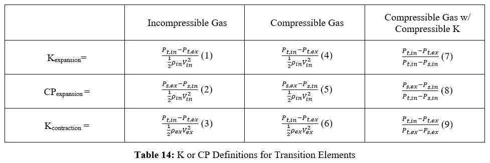
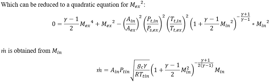
Flow Rate Calculations
With the above in mind for how K (or Cp) is calculated for each of the transition
element types, the momentum equation for each of the possible cases is outlined in
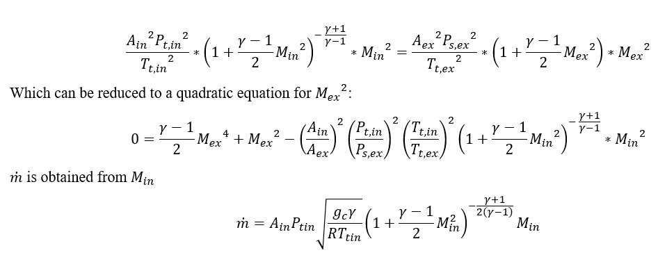
the table 14 below. These equations can be used to derive an expression for mass
flow rate, .
.
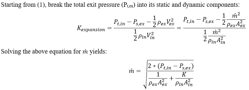
Formulation of for (1) – Kexpansion for an
Incompressible Gas:
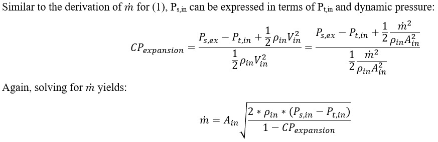
Formulation of for (2) – CPexpansion for an
Incompressible Gas:
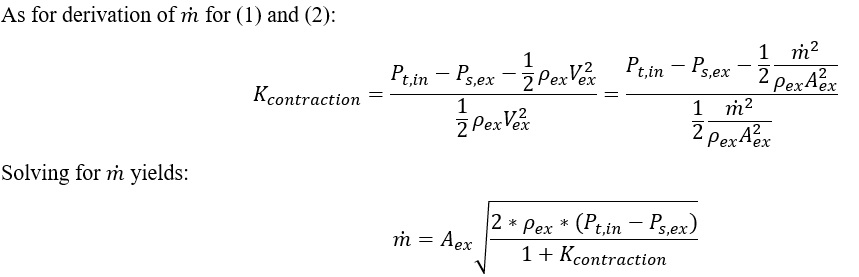
Formulation of for (3) – Kcontraction for an
Incompressible Gas:
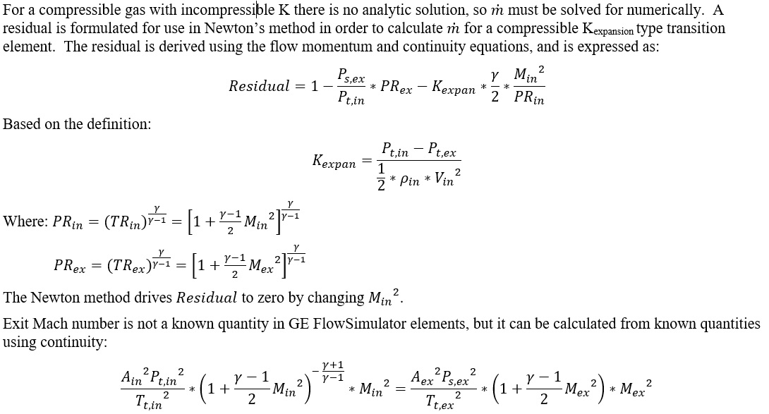
Formulation of for (4) – Kexpansion for a Compressible
Gas:
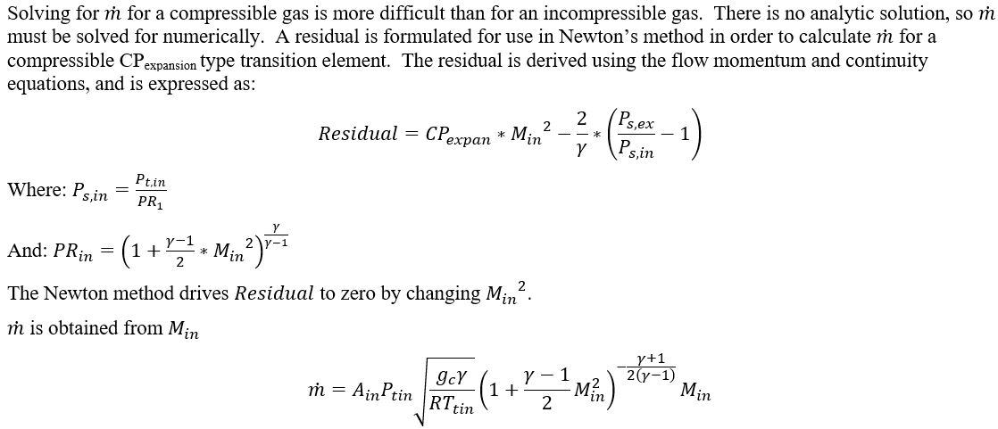
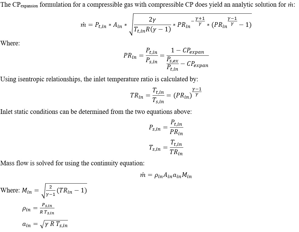
Formulation of for (5) – CPexpansion for a Compressible
Gas:
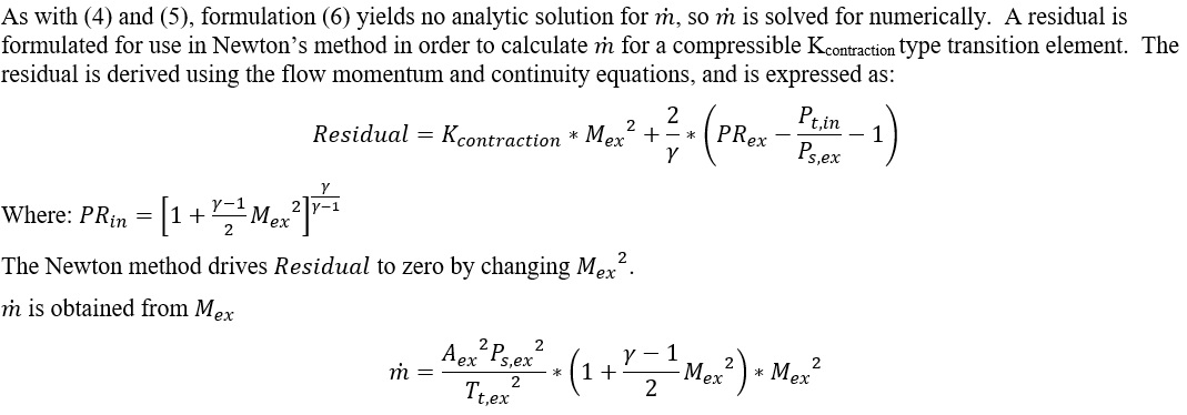
Formulation of for (6) – Kcontraction for a Compressible
Gas:
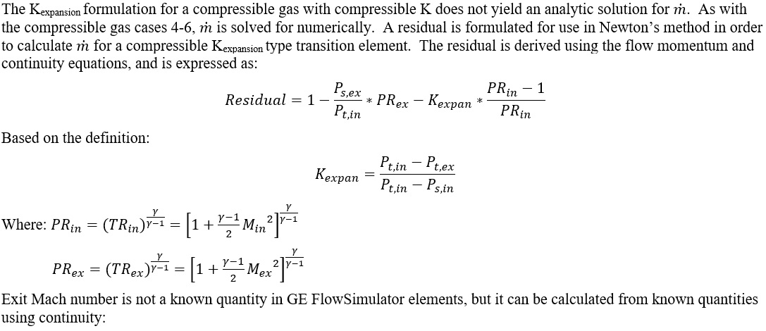
Formulation of for (7) – Kexpansion for a Compressible
Gas with Compressible K:
Formulation of for (8) – CPexpansion for a Compressible
Gas with Compressible CP:
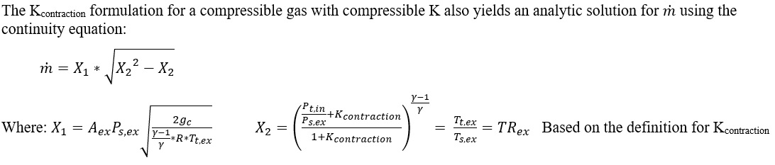
Formulation of for (9) – Kcontraction for a Compressible
Gas with Compressible K:
Additional Momentum Loss
For Additional Momentum loss, Portion of Upstream Dynamic Head loss, Exit K Loss refer Solver General theory section.
Transition Element Outputs
Outputs in file with “res” extension. Output units controlled by user setting in “Output Control” panel.

| Name | Description | Units ENG, SI |
|---|---|---|
| GEOMETRY: |
Expansion or contraction type that was finally used (which depends on flow direction). A list of possible geometries is as follows. EXPANSION_W_FIXED_K CONICAL_EXPANSION_BLEVINS CONICAL_EXPANSION_MILLER EXPANSION_W_FIXED_CP EXPANSION_W_FIXED_EFFEC ABRUPT_EXPANSION_SIMPLE ABRUPT_EXPANSION_MILLER CD_LOSS CONTRACTION_W_FIXED_K ABRUPT_CONTRACTION_SIMPLE ABRUPT_CONTRACTION_POLYNOM ABRUPT_CONTRACTION_MILLER1 ABRUPT_CONTRACTION_MILLER2 CONICAL_CONTRACTION_BLEVINS CONICAL_CONTRACTION_MILLER |
(None) |
| CROSS-SECTION: | Shape of channel cross-section (CIRCULAR or ARBITRARY) | (None) |
| FRICTION: | How friction was calculated (OFF, SWAMEE, or FIXED) | (None) |
| FLUID: |
Fluid compressibility option (INCOMPRESSIBLE, COMPRESSIBLE, or FULLY_COMPRESS) Fully compressible means the fluid is compressible and the K-relationship is compressible too. |
(None) |
| LENGTH | Length of the transition channel | inch, mm |
| INLET_AREA | Area at Transition inlet | inch2, m2 |
| EXIT_AREA | Area at Transition exit | inch2, m2 |
| DHIN | Hydraulic Diameter at Transition inlet | inch, mm |
| DHEX | Hydraulic Diameter at Transition exit | inch, mm |
| ROUGHNESS_TYPE: |
Type of roughness being used. SAND_GRAIN AVERAGE_ABSOLUTE ROOT_MEAN_SQUARE PEAK_TO_VALLEY |
(None) |
| ROUGHNESS | Roughness value (copy of input) | inch, mm |
| EQUIV_SAND_GRAIN_ROUGHNESS | Roughness value converted into a Sand-grain roughness so it can be used with the Colebrook-White relation | inch, mm |
| FMULT | Friction multiplier (copy of input, typically used in place of roughness) | (unitless) |
| DARCY_FRIC | Darcy friction factor at throat station | (unitless) |
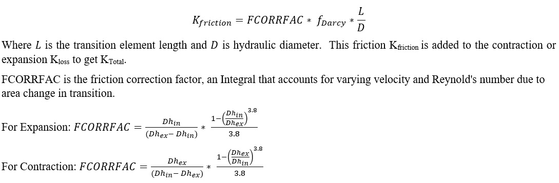
| FCORRFAC | Friction loss correction factor that accounts for inlet and exit area being different. If Ain=Aex, then FCORRFAC=1. | (unitless) |
| KFRIC | Loss coefficient attributable to friction | (unitless) |
| K_EXPAN | Expansion K parameter (Total Pressure Loss Coefficient) for this expansion geometry (could be a user input, calculated value, or table lookup depending on the setup) | (unitless) |
| CP_EXPAN | Expansion Cp (Static Pressure Recovery Coefficient) for this expansion geometry (could be a user input, calculated value, or table lookup depending on the setup) | (unitless) |
| EFFEC_EXPAN | Diffuser Effectiveness for this expansion geometry (could be a user input, calculated value, or table lookup depending on the setup) | (unitless) |
| K_EXPAN_TOTAL | Combination of K_EXPAN and friction effects | (unitless) |
| CP_TOT | Combination of CP_EXPAN and friction effects | (unitless) |
| EFFEC_TOT | Combination of EFFEC_EXPAN and friction effects | (unitless) |
| K_CONTRAC | Contraction K loss for this contraction geometry (could be a user input, calculated value, or table lookup depending on the setup) | (unitless) |
| K_CONTRAC_TOT | Combination of K_CONTRAC and friction effects | (unitless) |
| MINOR_FILLET_RADIUS |
Fillet radius at the throat (just a copy of the input value) Used only for the following sub-types: ABRUPT_CONTRACTION_MILLER2 |
inch, mm |
| K_EXPAN_RESULT | Back-calculated K. Should be the same as K_EXPAN_TOT | (unitless) |
| CP_RESULT | Back-calculated Cp. Should be the same as CP_TOT | (unitless) |
| EFFEC_RESULT | Back-calculated Effec. Should be the same as EFFEC_TOT | (unitless) |
| K_CONTRAC_RESULT | Back-calculated K. Should be the same as K_CONTRAC_TOT | (unitless) |
| CD_RESULT | Result calculated from actual mass flow rate divided by ideal mass flow rate. The ideal mass flow rate assumes either K=0, Cp=Cp_ideal, or Effec=1. | (unitless) |
| FLUID_EXIT_THETA | Exit Theta angle of fluid after going through K-exit losses (only shows if there are K-exit losses) | deg |
| FLUID_EXIT_PHI | Exit Phi angle of fluid after going through K-exit losses (only shows if there are K-exit losses) | deg |
| PTS | Driving pressure relative to the rotational reference frame (i.e. rotor) at the transition inlet. | psia, MPa |
| PSIN |
Static pressure relative to the rotational reference frame (i.e. rotor) at the transition inlet. Limited by critical pressure ratio for supersonic flows when inlet area is smaller than exit area. |
psia, MPa |
| PTEX | Total pressure relative to the rotational reference frame (i.e. rotor) at the transition exit including supersonic effects. | psia, MPa |
| PSEX |
Static pressure relative to the rotational reference frame (i.e. rotor) at the transition exit. Limited by critical pressure ratio for supersonic flows. |
psia, MPa |
| PSEB | Effective sink (static) pressure downstream of the transition. | psia, MPa |
| TTS | Total temperature of fluid relative to the rotational reference frame (i.e. rotor) at the transition inlet. | deg F, deg K |
| TSIN | Static temperature of fluid relative to the rotational reference frame (i.e. rotor) at the transition inlet. | deg F, deg K |
| TTEX | Total temperature of fluid relative to the rotational reference frame (i.e. rotor) at the transition exit. | deg F, deg K |
| TSEX | Static temperature of fluid relative to the rotational reference frame (i.e. rotor) at the transition exit. | deg F, deg K |
| QIN |
Heat added Positive values indicate heat added to the fluid; negative values indicate heat removed. |
Btu/s, W |
| INVEL | Velocity of fluid relative to the rotational reference frame (i.e. rotor) at the transition inlet. | ft/s, m/s |
| INMN | Mach number of fluid relative to the rotational reference frame (i.e. rotor) at the transition inlet. | (unitless) |
| INREYN | Reynolds number of fluid at the transition inlet. | (unitless) |
| EXVEL | Velocity of fluid relative to the rotational reference frame (i.e. rotor) at the transition exit. | ft/s, m/s |
| EXMN | Mach number of fluid relative to the rotational reference frame (i.e. rotor) at the transition exit. | (unitless) |
| EXREYN | Reynolds number of fluid at the transition exit. | (unitless) |
References
- Blevins, R. D., Applied Fluid Dynamics Handbook, Krieger Publications, 2003
-
Miller, D, Internal Flow Systems, Miller Innovations, 1990