Combustion Element
Combustion Element General Description
The combustion element in Flow Simulator is intended to model combustion reactions using chemical properties of reactants. The combustion element uses NASA’s Chemical Equilibrium with Applications (CEA) code for the reaction calculation. The CEA code accounts for the change in enthalpy and subsequent heat rise due to combustion. The Flow Simulator combustion element calculates the Rayleigh loss solution due to this heat rise to determine inlet and exit pressure and Mach number.
Quick Guide for Combustion Element Model Creation in the GUI
CEA Combustion element and Fuel Source element are available under Combustion Modeling section of element library.
CEA Combustion Element’s geometric input of exit area is mandatory. Users can add pressure losses, heat release damping and combustion efficiency options. Moreover, users can decide on the CEA run interval base on model run.
Combustion Element Input Variables
CEA Combustion Element inputs
| CEA Combustion Element Input Variables | ||
| Index | UI Name (. flo label) | Description |
| 1 | (COMBFLAG) |
Combustion Flag 0: do not perform combustion in this element. 1: perform combustion in this element. |
| 2 | Loss Option (LOSSFLAG) |
Total Pressure Loss Flag. Available loss options are: 0.0: No Pressure Loss 1.0: K-Loss Factor 2.0: Exit PT over Inlet PT
Note 1: Options 1 and 2 Include extra P total loss based on FWD_PLOSS and REV_PLOSS
Note 2: The Ptotal loss due to heat release is always calculated if temperature rises more than 1% through the element. |
| 3 | Exit Area (AREA) | Exit flow area of the combustion element |
| 4 | Forward Pressure Loss (FWD_PLOSS) | Forward flow pressure loss value based on loss flag |
| 5 | Reverse Pressure Loss (REV_PLOSS) | Reverse flow pressure loss value based on loss flag |
| 6 | Heat Release Damping (HR_DAMP) |
Heat Release Damping damps the temperature rise per iteration predicted by CEA.
Note: Value must be > 0 (very little temperature changes each iteration) and < or = 1.0 (full temperature change per iteration) |
| 7 | CEA Run Interval (RUN_INT) |
Iteration interval to run CEA. CEA is a relatively slow program and should not need to be called every flow solver iteration. Note 1: Default RUN_INT = 5. Note 2: If RUN_INT=1 CEA will be called every iteration. |
| 8 | Efficiency Type (EFF_FLAG) |
Efficiency Type Flag determines the type of efficiency to apply. See COMB_EFF |
| 9 | Combustion Efficiency (COMB_EFF) |
Available options are: 1.0: Heat Release Fraction is a fraction of the total heat release. Any heat not released in the element is carried downstream and will be released in a downstream combustion element if the COMB_EFF in the downstream combustion element is set high enough. 2.0: Total Fuel Fraction is a fraction of the total fuel (both burned and unburned) entering the element. 3.0: Fuel Fraction is a fraction of the unburned fuel entering the element.
Note: Values must be between 0 and 1. |
| 10 | Element Inlet Orientation: Tangential Angle (THETA) |
Angle between the element centerline at the entrance of the element and the reference direction. If the element is rotating or directly connected to one or more rotating elements, the reference direction is defined as parallel to the engine centerline and the angle is the projected angle in the tangential direction. Otherwise, the reference direction is arbitrary but assumed to be the same as the reference direction for all other elements attached to the upstream chamber.
THETA for an element downstream of a plenum chamber has no impact on the solution except to set the default value of THETA_EX. (See also THETA_EX) |
| 11 | Element Inlet Orientation: Radial Angle (PHI) |
Angle between the element centerline at the entrance of the element and the THETA direction. (spherical coordinate system)
PHI for an element downstream of a plenum chamber has no impact on the solution except to set the default value of PHI_EX. (See also PHI_EX) |
| 12 | Element Exit Orientation: Tangential Angle (THETA_EX) |
Angle between the orifice exit centerline and the reference direction. THETA_EX is an optional variable to be used if the orientation of the element exit differs from that of the element inlet.
The default value (THETA_EX = -999) will result in the assumption that THETA_EX = THETA.
Other values will be interpreted in the manner presented in the description of THETA. |
| 13 | Element Exit Orientation: Radial Angle (PHI_EX) |
Angle between the orifice exit centerline and the THETA_EX direction.
PHI_EX is an optional variable to be used if the orientation of the element exit differs from that of the element inlet.
The default (PHI_EX = -999) will result in the assumption that PHI_EX = PHI.
Other values will be interpreted in the manner presented in the description of PHI. |
Combustion Element Theory
The combustion element uses NASA’s Chemical Equilibrium with Applications (CEA) code for the reaction calculation. Reactants from the upstream chamber of a combustion element are sent to CEA, and combustion products and resultant temperatures are returned to the downstream chamber. The CEA code accounts for the change in enthalpy and subsequent heat rise due to combustion. The Flow Simulator combustion element calculates the Rayleigh loss solution due to this heat rise to determine inlet and exit pressure and Mach number.
Rayleigh Loss Solution
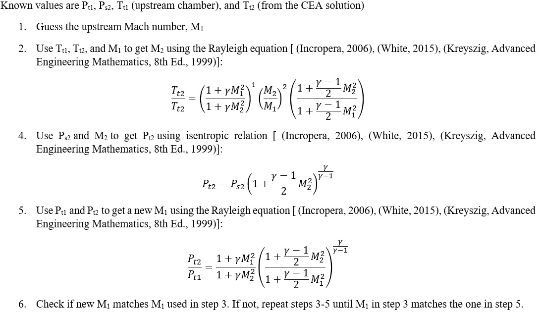
In the combustion element, the total pressure loss due to combustion heat addition is modeled by satisfying the Rayleigh equations. Total pressure loss due to heat addition is typically small (less than 1 psi). Flow Simulator combustion elements use an iterative procedure to calculate pre- and post-combustion Mach numbers. The procedure is as follows
Efficiency Modeling
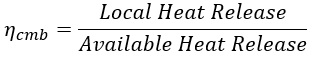
- The combustor efficiency based on Heat Release Fraction is defined as:
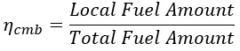
- Fuel amount that should be burned up through that combustion element
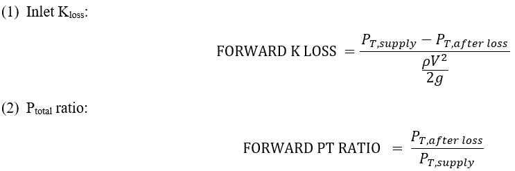
Loss Calculation
Combustion Element Output Variables
Outputs in file with “res” extension. Output units controlled by user setting in “Output Control” panel.
![]()
| Name | Description | Units ENG, SI |
|---|---|---|
|
FLOW: FLOW: %W2 & MASSFLOWRATE |
Flow rates in %W2 and [PPS]or [kg/s] | (None) & (Lbm/s or kg/s) |
| COMBUSTION |
Flag specifying whether combustion is active in the element. (Copy of the user input.) |
(flag) |
| CROSS_STREAM_AREA |
Flow area. (Copy of the user input.) |
inch2, m2 |
| PT_LOSS: HEAT_ADDITION |
Total pressure loss due to heat addition (Rayleigh Losses). Positive value is a loss in pressure. |
Psi, MPa |
| PTOTAL | Total pressure before and after combustion in the element. | Psi, MPa |
| PSTATIC | Static pressure before and after combustion in the element. | Psi, MPa |
| TTOTAL | Total temperature before and after combustion in the element. | deg F, K |
| MN | Fluid Mach number before and after combustion in the element. | (unitless) |
| VEL | Fluid velocity before and after combustion in the element. | ft/s, m/s |
| ENTH | Enthalpy of the fluid before and after combustion in the element. | BTU/lbm, KJ/kg |
| REACTANT | Column of combustion reactants prior to combustion in the element. | (N/A) |
| PRODUCTS | Column of combustion products after combustion in the element. | (N/A) |
| UNBURNED_FUEL | Column of remaining unburned fuel after combustion that is passed downstream to be burned in subsequent combustion elements. This output is only printed when combustion efficiency as a fraction of fuel is used (EFF_TYPE=2 or 3). | (N/A) |
| MASS_FR | Column of mass fractions for each reactant/product before and after combustion in the element. | (fraction) |
| MFLOW | Column of mass flows for each reactant/product before and after combustion in the element. | Lbm/s, kg/s |
| MOLE_FR | Column of mole fractions for each reactant/product before and after combustion in the element. | (fraction) |
| EFF_TYPE |
Efficiency type flag (Copy of the user input.) |
(flag) |
| COMB_EFFIC | Combustion efficiency in the element. | (fraction) |
| HEAT_RELEASE | Heat released during combustion in the element. | BTU/s, W |
| HR_TOT_AVL | Total heat release available from all upstream and current combustion elements (assumes efficiency = 1 if EFF_TYPE=1.0). | BTU/s, W |
| MFUEL | Mass flow of the fuel entering this element as if there were no combustion upstream. Used to keep track of the fuel air ratio as dilution and cooling flow is added to the flame passage. | Lbm/s, kg/s |
| FUEL_HEATING_VALUE | Heating value of the fuel after combustion in the current element and all upstream combustion elements. This = HR_TOT_AVL / MFUEL | BTU/lbm, KJ/Kg |
| HR_TOT_APP | Total heat release applied in all upstream and the current combustion elements after taking efficiency into account. This output is only visible when combustion efficiency as a fraction of heat release is used (EFF_TYPE=1.0). | BTU/s, W |
| HR_UP_APP | Total heat release applied in the upstream combustion elements after taking efficiency into account. This output is only visible when combustion efficiency as a fraction of heat release is used (EFF_TYPE=1.0). | BTU/s, W |
| HR_ELEM | Total heat release applied in the current combustion element after taking efficiency into account this output is only visible when combustion efficiency as a fraction of heat release is used (EFF_TYPE=1.0). HR_ELEM = HR_TOT_APP - HR_UP_APP | BTU/s, W |
| RHO | Density of the outlet fluid. | lbm/ft3, kg/m3 |
| VISC | Dynamic viscosity of the outlet fluid. |
lbm/ (hr-ft) |
| CP | Heat capacity at constant pressure (specific heat) of the outlet fluid. |
BTU/ (lbm-R) |
| MW | Molecular weight of the outlet fluid. |
lbm/ lbmole |
| GAMMA | Ratio of specific heats of the outlet fluid. | (unitless) |
| COND | Conductivity of the outlet fluid. |
BTU/ (hr-ft-R) |
| PR | Prandtl number of the outlet fluid. | (unitless) |
References
- White, Frank M., Fluid Mechanics, 8th Ed., McGraw - Hill, 2015
- Incropera, F. and Dewitt, D. Fundamentals of Heat and Mass Transfer, 6th Edition, John Wiley & Sons, 2006
- Gordon, S., McBride, B.J., Computer program for calculation of complex chemical equilibrium compositions and applications, NASA Technical Reports, 1994