Fixed Flow Elements
Fixed Flow Element General Description
The Fixed Flow Element is used to supply a constant flow rate either to or from the element/component. Flow is assumed to leave the element at the temperature specified for the upstream chamber. The momentum can be transferred downstream by providing the Exit area, angles, and rotation inputs. When flow is put into a model through a fixed flow element, care must be taken that the temperature in the upstream chamber has any needed correction made for rotational effects to yield the appropriate relative temperature for the downstream chamber. If the downstream chamber is an inertial chamber an absolute temperature must be supplied. If not, consideration must be given to the downstream chamber’s rotational velocity.
Quick Guide for Fixed Flow Element Creation in the GUI
Fixed Flow Elements are available under both Compressible Gas Elements & Incompressible Liquid Elements sections. There are four different subtypes of Fixed Flow elements available in FlowSimulator basically differing from the input that are supplied. They are
- Mass Flow Rate - Value input for mass flow rate
- Mass Flow Rate (% Core) – Percentage with respect to Reference Flow Rate (Refer General Data Section)
- Volumetric Flow rate - Value input for Volumetric flow rate
- Blank End - The blank end acts as a flow source, but with the flow pre-set to zero
Fixed Flow Element Inputs
Table of the inputs for the Fixed Flow Element.
| Element Specific Fixed Flow Element Input Variables | ||
| Index | UI Name (. flo label) | Description |
| 1 | Flow Input (SUB_TYPE) |
Element subtype determines how FLOW variable is interpreted. 1.0: Mass Flow rate is input 2.0: Mass Flow rate is input as %WREF 3.0: Volumetric Flow rate is input 4.0: Blank End with no Input (Default value = 1.) |
| 2 | Flow (FLOW) | Element fixed flow rate |
| 3 | Exit Area (AREA) | Physical area used to calculate exit velocity (Optional input). |
| 4 | Element Inlet Orientation: Tangential Angle (THETA) |
Angle between the element centerline at the entrance of the element and the reference direction.
If the element is rotating or directly connected to one or more rotating elements, the reference direction is defined as parallel to the engine centerline and the angle is the projected angle in the tangential direction. Otherwise, the reference direction is arbitrary but assumed to be the same as the reference direction for all other elements attached to the upstream chamber.
Element exit orientation for the theta angle is the same in the inlet THETA for fixed flow element types. |
| 5 | Element Inlet Orientation: Radial Angle (PHI) |
Angle between the element centerline at the entrance of the element and the THETA direction. (spherical coordinate system)
Element exit orientation for the phi angle is the same in the inlet PHI for fixed flow element types. |
| 6 | Rotor Index (RPMSEL) |
Reference rotor index for user-supplied swirl. Stationary (Database Value = 0.0) Rotor 1 (Database Value = 1.0): Points to general data Shaft 1 Rotor Speed. Rotor 2 (Database Value = 2.0): Points to general data Shaft 2 Rotor Speed Rotor 3 (Database Value = 3.0): Points to general data Shaft 3 Rotor Speed Rotates with Air (database Value = -1.0): Element RPM is based on upstream fluid RPM |
| 7 | Radius (RADIUS) |
Radius. Radial distance between the fixed flow and the engine centerline. (Do not use zero unless the fixed flow is not rotating) |
Fixed Flow Element Theory
If the element is declared to be subtype 1 & Subtype 3, the flow going into the downstream chamber will be the value input for flow (FLOW). For subtype 2, the flow going into the downstream chamber will be:
![]()
If Exit Area is greater than 0, then
For Incompressible flow:
![]()
For Compressible Flow:
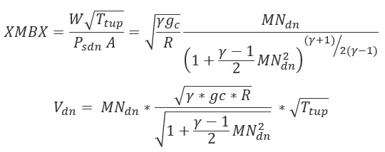
XMBX = Total pressure flow parameter
| Nomenclature: | Subscripts: |
| W: Mass flow rate | up: Upstream station |
| Tt: Total Temperature | dn: Downstream station |
| Pt: Total pressure | ref: Reference |
| Ps: Static pressure | |
| Specific heat Ratio | |
| R: Gas Constant | |
| Density | |
| MN: Vena Contracta Mach Number | |
| gc: Gravitational Constant |
Fixed Flow Element Outputs
The following listing provides details about fixed flow element output variables.
| Name | Description | Units |
|---|---|---|
| ELEMENT_RPM |
RPM (Rotor index) (Usually an echo of the user input unless modified inside Flow Simulator.) |
rad/min |
| RAD |
Radius (Usually an echo of the user input unless modified inside Flow Simulator.) |
in, m |
| AREA |
Exit area. (Usually an echo of the user input unless modified inside Flow Simulator.) |
inch2, m2 |
| Flow | Element Flow Rate | Lbm/s, Kg/s |
| PTC | Driving pressure relative to the rotational reference frame (i.e. rotor) at the restriction inlet. | psi, mPa |
| PSC | Effective sink (static) pressure downstream of the restriction. | psi, mPa |