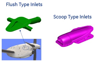
Naca Scoop Element
Naca Scoop Element General Description
A NACA duct also sometimes called a NACA scoop or NACA inlet, is a common form of low-drag air inlet design. A NACA duct allows air to flow into an internal duct, often for cooling purposes, with a minimal disturbance to the flow. The design was originally called a submerged inlet, since it consists of a shallow ramp with curved walls recessed into the exposed surface of a streamlined body. FlowSimulator Naca scoop element calculate pressure recovery factor & flow rates through scoop/flush type inlets for given geometry & operating conditions.
Quick Guide for Naca Scoop Element Creation in the GUI
There are three subtypes of Naca Scoop elements available in FlowSimulator. This element is available only for Compressible (e.g. gas systems) analysis. The various subtypes are
- Scoop inlets
- Flush Inlets (NACA based Formulations)
- Flush Inlets (ESDU based formulations)
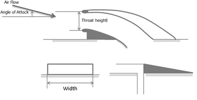
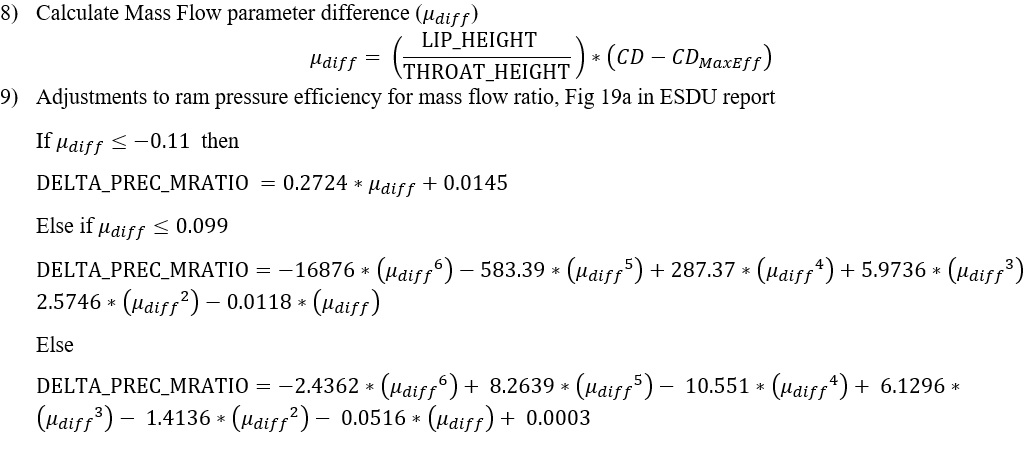
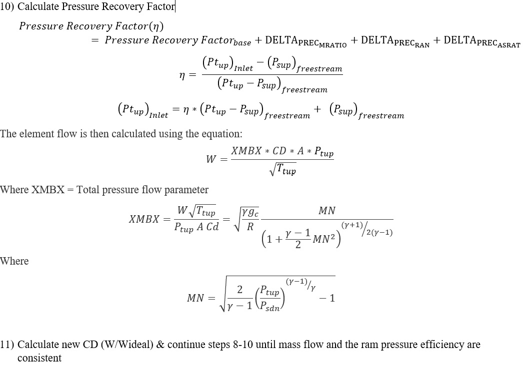
Typical Geometry inputs that are required to model Naca Inlets are provided in the below images
Flush Type:

Scoop type:
Naca Scoop Element Inputs
Table of the inputs for the Naca Scoop Element.
| Element Specific NACA Inlet Scoop Element Input Variables | ||
| Index | UI Name (. flo label) | Description |
| 1 |
Inlet Type (SUBTYPE) |
Inlet Scoop subtype. 0.0: NACA Scoop Formulation 1.0: NACA Flush Formulation 2.0: ESDU Flush Formulation (Default value = 0.0) |
| 2 | Nacelle Distance (NACELLE_DIST) | Distance from leading edge of the nacelle to the start of the inlet. |
| 3 |
Throat Height (THROAT_HEIGHT) |
Inlet throat height |
| 4 |
Throat Width (WIDTH) |
Inlet throat width |
| 5 |
Lip Height (LIP_HEIGHT) |
Flush lip height *Used only in ESDU-Flush |
| 6 |
Ramp Angle (RAMP_ANGL) |
Ramp angle *Used only in ESDU-Flush |
| 7 | Element Inlet Orientation: Tangential Angle (THETA) |
Angle between the element centerline at the entrance of the element and the reference direction. If the element is rotating or directly connected to one or more rotating elements, the reference direction is defined as parallel to the engine centerline and the angle is the projected angle in the tangential direction. Otherwise, the reference direction is arbitrary but assumed to be the same as the reference direction for all other elements attached to the upstream chamber.
THETA for an element downstream of a plenum chamber has no impact on the solution except to set the default value of THETA_EX. (See also THETA_EX) |
| 8 | Element Inlet Orientation: Radial Angle (PHI) |
Angle between the element centerline at the entrance of the element and the THETA direction. (spherical coordinate system)
PHI for an element downstream of a plenum chamber has no impact on the solution except to set the default value of PHI_EX. (See also PHI_EX) |
|
9 10 11 |
Exit K Loss: Axial (K_EXIT_Z) Tangential (K_EXIT_U) Radial (K_EXIT_R) |
Head loss factors in the Z, U, and R directions based on the spherical coordinate system of theta and phi. (Default value provides no loss).
Refer General solver theory sections for more details about this input |
| 12 | Element Exit Orientation: Tangential Angle (THETA_EX) |
Angle between the orifice exit centerline and the reference direction. THETA_EX is an optional variable to be used if the orientation of the element exit differs from that of the element inlet.
The default value (THETA_EX = -999) will result in the assumption that THETA_EX = THETA.
Other values will be interpreted in the manner presented in the description of THETA. |
| 13 | Element Exit Orientation: Radial Angle (PHI_EX) |
Angle between the orifice exit centerline and the THETA_EX direction.
PHI_EX is an optional variable to be used if the orientation of the element exit differs from that of the element inlet.
The default (PHI_EX = -999) will result in the assumption that PHI_EX = PHI.
Other values will be interpreted in the manner presented in the description of PHI. |
| 14 | Portion of Ustrm Chamb. Dyn. Head Lost (DQ_IN) | Inlet dynamic head loss. Refer General solver theory sections for more details about this input |
Naca Scoop Element Theory Manual
| Nomenclature: | |
| W: Mass flow rate | Specific heat Ratio |
| Tt: Total Temperature | R: Gas Constant |
| Pt: Total pressure | Density |
| Ps: Static pressure | Cp: Specific Heat |
| MN: Mach Number | gc: Gravitational Constant |
| V: Velocity | |
| Subscripts: | |
| up: Upstream station | dn: Downstream station |
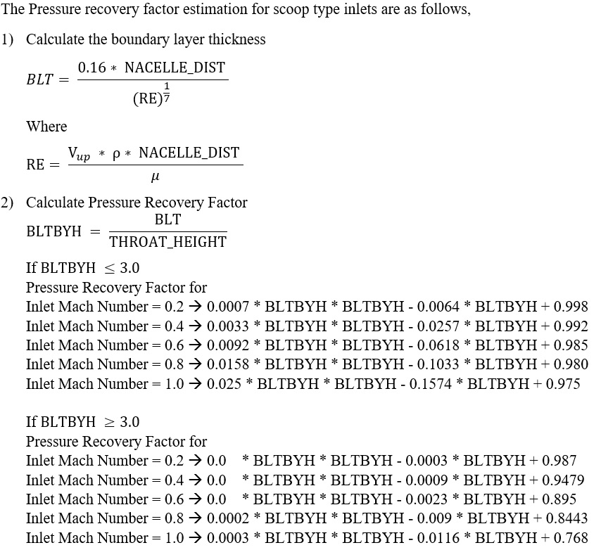
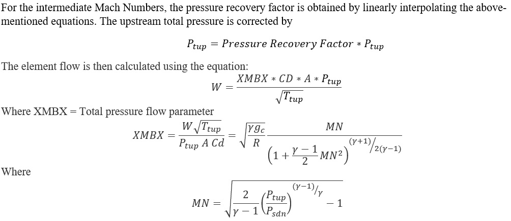
Scoop Type Inlets
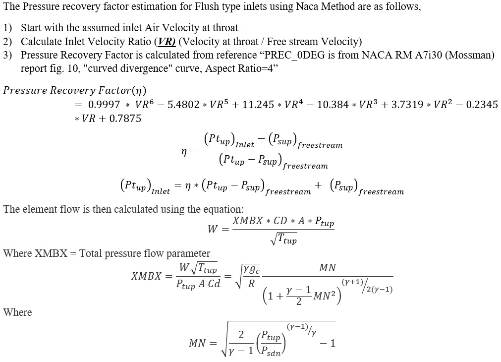
Flush Type Inlets (Naca Method)
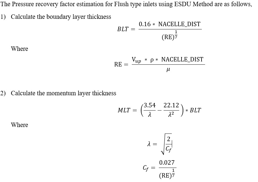
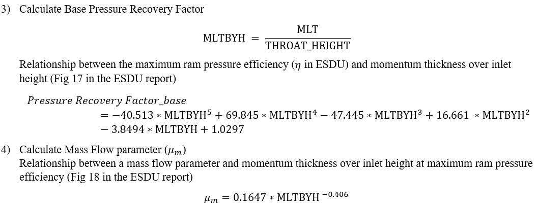
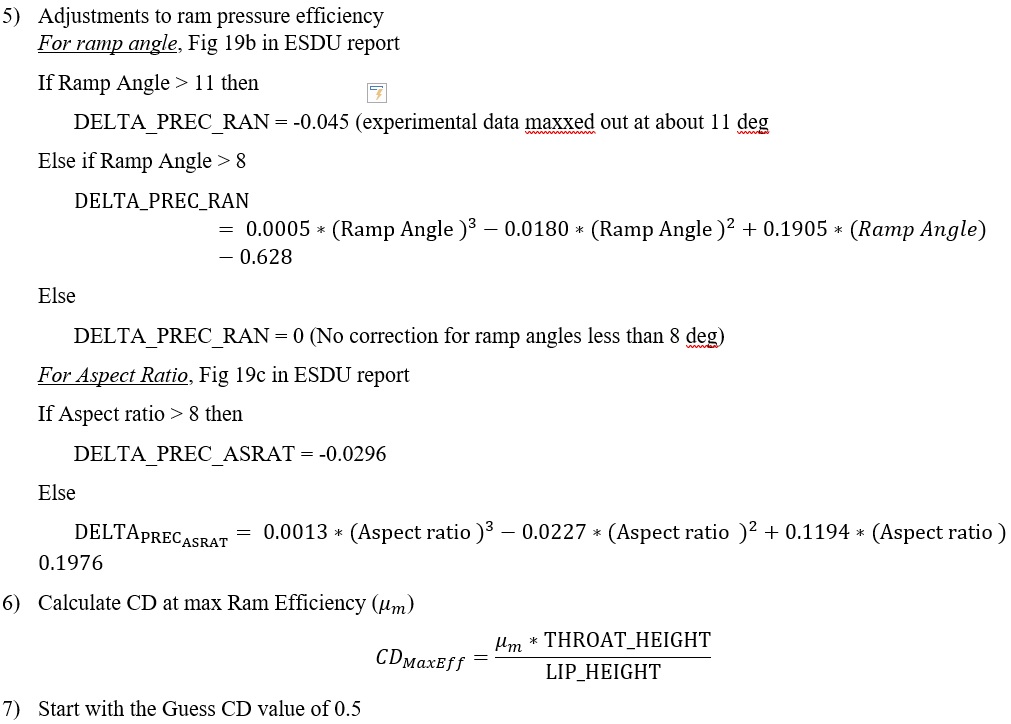
Flush Type Inlets (ESDU Method)
Additional Momentum Loss
For Additional Momentum loss, Portion of Upstream Dynamic Head loss, Exit K Loss refer Solver General theory section.
Naca Scoop Element Outputs
The following table listing contains output variables common to all Inlet scoop types.
| Name | Description | Units |
|---|---|---|
| UPSTREAM: PT | Upstream (station 0) driving pressure (like PTS of other element types). | psi, mPa |
| UPSTREAM: PS | Upstream (station 0) static pressure. | psi, mPa |
| UPSTREAM: TT | Upstream (station 0) total temperature. | deg F, K |
| UPSTREAM: TS | Upstream (station 0) static temperature. | deg F, K |
| UPSTREAM: MN | Upstream (station 0) Mach number. | (unitless) |
| UPSTREAM: VEL | Upstream (station 0) velocity. | ft/s, m/s |
| UPSTREAM: AOA | Angle of attack of incoming air (station 0). | deg |
| THROAT: PT | Throat (station 1) driving pressure (like PTS of other element types). | psi, mPa |
| THROAT: PS | Throat (station 1) static pressure. | psi, mPa |
| THROAT: TT | Throat (station 1) total temperature. | deg F, K |
| THROAT: TS | Throat (station 1) static temperature. | deg F, K |
| THROAT: MN | Throat (station 1) Mach number. | (unitless) |
| THROAT: VEL | Throat (station 1) velocity. | ft/s, m/s |
| THROAT: VRAT | Velocity ratio (Vstation1 / Vstation). | (unitless) |
| IDEAL_MDOT | Ideal mass flow rate. | lbm/sec |
| CD | Actual mass flow rate divided by ideal mass flow rate. | (unitless) |
| INLET_HEIGHT |
Inlet throat height. (Echo of the user input value.) |
in, m |
| INLET_WIDTH |
Inlet throat width. (Echo of the user input value.) |
in, m |
| INLET_AREA | Inlet throat area (height * width). | inch2, m2 |
| INLET_ASPECT_RATIO | Inlet throat aspect ratio (width / height). | (unitless) |
The following table listing contains output variables unique to the NACA Inlet Scoop (SUBTYPE=0).
| Name | Description | Units |
| NACELLE_DIST |
Distance from leading edge of the nacelle to the start of the Inlet. (Echo of the user input value.) |
in, m |
| REY | Reynolds Number based on distance from the nacelle leading edge. | (unitless) |
| BND_LAY_THK | Turbulent flat plate boundary layer thickness. | in, m |
| P_RATIO | Pressure ratio (PT1 / PT0), (PTinlet / PTfreestream) | (unitless) |
The following table listing contains output variables unique to the NACA Flush Scoop (SUBTYPE=1).
| Name | Description | Units |
| RAM_P_EFF | Ram Pressure Efficiency (recovery factor) after adjustments (PT1-PS0)/(PT0-PS0). | (unitless) |
The following table listing contains output variables unique to the ESDU Flush Scoop (SUBTYPE=2).
| Name | Description | Units |
| INLET_LIP_HEIGHT |
Flush lip height. (Echo of the user input value.) |
in, m |
| NACELLE_DIST |
Distance from leading edge of the nacelle to the start of the Inlet. (Echo of the user input value.) |
in, m |
| REY | Reynolds Number based on distance from the nacelle leading edge. | (unitless) |
| BND_LAY_THK | Turbulent flat plate boundary layer thickness. | in, m |
| MOM_LAY_THK | Turbulent flat plate momentum layer thickness. | in, m |
| RAMP_ANGLE |
Ramp angle. (Echo of the user input value.) |
deg |
| RAM_P_EFF | Ram Pressure Efficiency after adjustments (PT1-PS0)/(PT0-PS0), ETTA in ESDU paper. | (unitless) |
| BASE_EFF | Ram Pressure Efficiency before adjustments (PT1-PS0)/(PT0-PS0). | (unitless) |
| MFLO_COR | Delta Ram Pressure Efficiency due to the mass flow not equal to full mass flow. | (unitless) |
| RAMP_ANG_COR | Delta Ram Pressure Efficiency due to the ramp angle. | (unitless) |
| ASRAT_COR | Delta Ram Pressure Efficiency due to the aspect ratio. | (unitless) |
References
- ESDU Report 86002, The Royal Aeronautical Society, “Drag and pressure recovery characteristics of auxilary air inlets at subsonic speeds, 2004
- NACA Report 5120, Charles W Frick, Wallace F Davis, Laurce M. Randall, and Emmet A Mossman, “An experimental investigation of NACA submerged duct entrances, 1951
- NACA Report R-72156, Laurce M. Randall, and Emmet A Mossman “An experimental investigation of the design variables for NACA submerged duct entrances, 1948
- NACA Report A8F21, Norman J., Martin, Curt A. Holshauser, “An experimental investigation at large scale of several configurations of an NACA submerged air intake, 1954
- NACA Report A8I29, Charles F. Hall, Joseph L. Frank, “Ram recovery characteristics of NACA submerged inlets at high subsonic speeds, 1948
- NACA Report RML50H15, P. Kenneth Perpont, Robert R. Howell, “Low speed investigation of a submerged air scoop with and without boundary layer suction, 1951
- NACA Report L57B07, John S Dennard, “A transonic investigation of the mass flow and pressure recovery characteristics of several types of auxillary air inlets, 1957
- NACA Report 2323, Alvin H Sacks, John R Spreiter, “Theoretical investigation of submerged inlets at low speeds, 1951