Positive Displacement Pump Element
Positive Displacement Pump General Description & Quick Guide
The Positive Displacement pump element routine simulates only for Incompressible Liquids. In Principle the Positive displacement pump behaves like a Fixed Flow element where the flow gets calculated from volumetric displacement provided by manufacturer for the specific pump. The PD pump model is based on a non-dimensional loss coefficient model developed by Wilson. (Ref: Wilson, W. “Performance criteria for positive displacement pumps and fluid motors”, ASME Semi-annual Meeting, paper No. 48-SA-14, 1948.
Positive Displacement Pump Element Inputs
Table of the inputs for the Positive Displacement Element.
| Element Specific Positive Displacement Pump Element Input Variables | ||
|---|---|---|
| Index | Field | Description |
| 1 | Pump Type (SUBTYPE) |
Positive displacement pump subtypes. (No Meaning) Default =1 |
| 2 | Speed (SPEED) | Pump shaft rotation speed in revolutions per minute |
| 3 | Volumetric Displacement (VOL_DISP) | Maximum Volumetric Displacement per cycle |
| 4 | Pump Leakage Coefficient (LEAK_COEFF) | The leakage coefficient characterizes the leakage flow which occurs within the pump. (Unitless) |
| 5 | Coulomb Friction Coefficient (COULOMB_COEFF) | Coulomb Friction Coefficient is the friction between the moving part (gear, vane, or piston) on the stationary part (casing or cylinder). (Unitless) |
| 6 | Viscous Friction Coefficient (VISCOUS_COEFF) | Viscous Friction Coefficient is the friction between the moving fluid and the casing or cylinder wall (Unitless) |
| 7 | Flow Efficiency Option (LEAK_OPT) |
There are two ways to specify flow efficiency: 1: Fixed Leakage Coefficient 2: Leakage Coefficient vs. Speed 3: Leakage Coefficient vs. Delta.P vs. Speed 11: Fixed Volumetric Efficiency 12: Volumetric Efficiency vs. Speed 13: Volumetric Efficiency vs. Delta.P vs. Speed |
| 8 | Volumetric Efficiency | Fixed Volumetric Efficiency |
| 10 | Exit Area (EXIT_AREA) | Area at the pump’s exit. This input helps to account for dynamic pressure exiting the pump. |
| 11 | Portion of Ustrm Chamb. Dyn. Head Lost (DQ_IN) | Inlet dynamic head loss. Refer General solver theory sections for more details about this input |
| 12 | Element Inlet Orientation: Tangential Angle (THETA) |
Angle between the element centerline at the entrance of the element and the reference direction. If the element is rotating or directly connected to one or more rotating elements, the reference direction is defined as parallel to the engine centerline and the angle is the projected angle in the tangential direction. Otherwise, the reference direction is arbitrary but assumed to be the same as the reference direction for all other elements attached to the upstream chamber.
THETA for an element downstream of a plenum chamber has no impact on the solution except to set the default value of THETA_EX. (See also THETA_EX) |
| 13 | Element Inlet Orientation: Radial Angle (PHI) |
Angle between the element centerline at the entrance of the element and the THETA direction. (spherical coordinate system)
PHI for an element downstream of a plenum chamber has no impact on the solution except to set the default value of PHI_EX. (See also PHI_EX) |
| 14 | Element Exit Orientation: Tangential Angle (THETA_EX) |
Angle between the orifice exit centerline and the reference direction. THETA_EX is an optional variable to be used if the orientation of the element exit differs from that of the element inlet.
The default value (THETA_EX = -999) will result in the assumption that THETA_EX = THETA.
Other values will be interpreted in the manner presented in the description of THETA. |
| 15 | Element Exit Orientation: Radial Angle (PHI_EX) |
Angle between the orifice exit centerline and the THETA_EX direction.
PHI_EX is an optional variable to be used if the orientation of the element exit differs from that of the element inlet.
The default (PHI_EX = -999) will result in the assumption that PHI_EX = PHI.
Other values will be interpreted in the manner presented in the description of PHI. |
| 16 | Fluid Compressibility Mode (FLUID_MODE) |
The user can choose which solution algorithm to use. By Default, 2: Incompressible Liquid |
| 17 | Mechanical Efficiency Option (MECH_EFF_OPT) |
Ways to specify Mechanical efficiency: 0: Friction Coefficients 11: Fixed Mechanical Efficiency 12: Mechanical Efficiency vs. Speed 13: Mechanical Efficiency vs. Delta.P vs. Speed |
| 18 | Mechanical Efficiency (MECH_EFF) | Fixed Mechanical Efficiency |
| 19 | TBL1_RPM/ TBL2_RPM/ TBL3_SPEED/ TBL4_SPEED |
Independent variable curve for shaft speed Should be in ascending order |
| 20 | TBL1_LEAK_COEFF/ TBL2_LEAK_COEFF |
Dependent variable curve for leakage coefficient Unitless |
| 21 | TBL2_DELTAP/ TBL4_DELTAP | Independent variable curve Delta Pressure Rise across Pump |
| 22 | TBL3_VOL_EFF /TBL4_VOL_EFF | Dependent variable curve Volumetric Efficiency Table |
Positive Displacement Theory Manual
Mass Flow rate Calculation
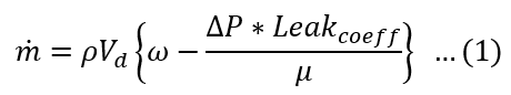
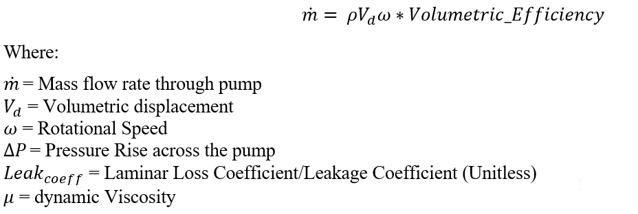
The Flow rate for a give pump is given by
If Leakage Coefficient is provided
If Volumetric Efficiency is provided
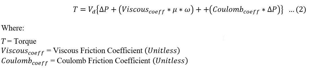
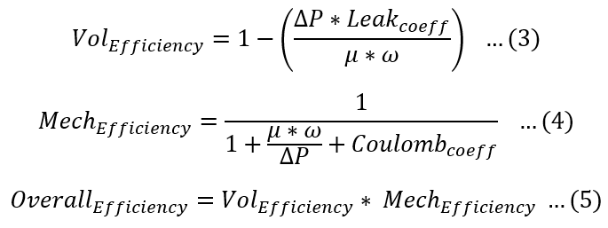
Addition to this the efficiencies & torque across the pump is also calculated.
Additional Momentum Loss
For Additional Momentum loss, Portion of Upstream Dynamic Head loss, refer Solver General theory section.
Positive Displacement Element Outputs
The following listing provides details about conventional orifice output variables.
| Name | Description | Units |
|---|---|---|
| DQ_IN |
Portion of Ustrm Chamb. Dyn. Head Lost (Usually an echo of the user input unless modified inside Flow Simulator.) |
Flag |
|
Axial (K_EXIT_Z) Tangential (K_EXIT_U) Radial (K_EXIT_R) |
Exit K Loss (Usually an echo of the user input unless modified inside Flow Simulator.)
|
Unitless |
| ELEMENT_THETA |
Tangential Angle (Usually an echo of the user input but converted to radians.) |
radians |
| ELEMENT_PHI |
Radial Angle (Usually an echo of the user input but converted to radians.) |
radians |
| REL_INLET_ANGLE | It is a relative inlet angle calculated based on upstream chamber velocity | Deg |
| IDEAL_FLOW | (Total flow – Leakage flow) | Lbm/s, Kg/s |
| SPPED |
Pump Speed (Usually an echo of the user input unless modified inside Flow Simulator.) |
RPM |
| LEAKAGE_FLOW | Leakage Flow | Lbm/s, Kg/s |
| EXIT_AREA |
Exit area used for calculating exit conditions of the orifice element. This output is only printed when an exit area is used (EXIT_AREA>0). A default value of 0 has no effect on exit conditions. (Output is an echo of the user input.) |
inch2, m2 |
| VOL_EFFIC | Volumetric Efficiency | (Unitless) |
| LEAKAGE_COEFF | Leakage Coefficient | (Unitless) |
| MECH_EFFIC | Mechanical Efficiency | (Unitless) |
| COULOMB_COEFF | Coulomb Friction Coefficient. | (Unitless) |
| VISCOUS_COEFF | Viscous Friction Coefficient | (Unitless) |
| HYDRAULIC_POWER | Hydraulic Power | HP |
| SHAFT_HPOWER | Shaft Power | HP |
| OVERALL_EFFIC | Overall Efficiency | (Unitless) |
| TORQUE | Torque | Ft-lbm, N-m |
| PTS | Driving pressure relative to the rotational reference frame (i.e. rotor) at the restriction inlet. | psi, mPa |
| PTEX | Total pressure relative to the rotational reference frame (i.e. rotor) at the restriction exit including supersonic effects. | psi, mPa |
| PSEX |
Static pressure relative to the rotational reference frame (i.e. rotor) at the restriction exit. Limited by critical pressure ratio for supersonic flows. |
psi, mPa |
| PSEB | Effective sink (static) pressure downstream of the restriction. | psi, mPa |
| TTS | Total temperature of fluid relative to the rotational reference frame (i.e. rotor) at the restriction inlet. | deg F, K |