Junction Elements
Junction Element General Description
Junction element is a 3-armed element and there are two Flow Simulator junction elements available. Both can be used in compressible and incompressible flow simulations. These elements are used to model different combining and dividing flow configurations, except, all 3 arms cannot have incoming or exiting flow at the same time. The 6 different flow configurations are listed below.
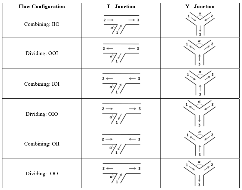
The junction arm numbering convention shown in the above table, is in accordance with data available in (Miller, 1990).
Quick Guide for Junction Element Model Creation in GUI
Both T-Junction and Y-Junction elements can be found under both “Compressible Gas Elements” & “Incompressible Liquid Elements” - “Junctions” section;

Geometric inputs of T-Junction (and Y-Junction) angle between Arms 1 & 2 (angle between minor arms), through pipe diameter (principle pipe diameter), and branch diameter (minor pipe diameter) are mandatory inputs. Apart from these, inputs like rotor index and radius are required if rotation effects are wanted to be included, and reference backflow angle is required if the backflow effects are wanted to be included. Descriptions about each input is described below in “Junction Element Inputs” section.
Each junction arm is associated with an internal momentum chamber. These chambers are hidden and not displayed on Graphical User Interface. However, their initial values can be set under Junction Element Property Editor.
Note 1:Flow angles must be defined according to flow configuration and must be consistent with neighbor elements’ flow angles. If a T-junction is provided with a bend angle, 𝛼 > 90°, then Flow Simulator solver swaps Arm 2 and Arm 3 and sets the new bend angle as 𝛼 = 180° – 𝛼. This ensures that the proposed numbering convention is applied properly during the simulation.
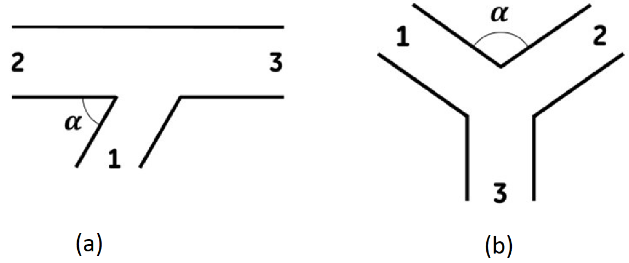
Figure: Arm numbering convention for (a) T-Junction and (b) Y-Junction
Junction Elements Input Variables
Table of the inputs specific for the Junction Element.
| Index | UI Name (. flo label) | Description |
| 1 | Junction Type (SUB_TYPE) |
Type of junction: 1: T-Junction 2: Y-Junction 3: Momentum Element |
| 2 | Flow Equation Type (FLUID_MODE) |
User can select the solution algorithm: Compressible Gas Incompressible Gas Incompressible Liquid |
| 3 | Loss Calculation Method (LOSS_METHOD) |
User can select one of the 3 loss calculation method: Interpolate Between Junction Angle K-Loss Tables Use K-Loss from Tables with Nearest Angle Use User Defined Junction K-Tables |
| 4 |
Through Pipe Diameter Principle Pipe Diameter Upstream (Arm 1) Area (MAJOR_DIAM) |
Diameter of the straight-through-pipe flow legs for T-Junction Diameter of the principal (combined) flow leg for Y-Junction Diameter of the upstream (Arm 1) of Momentum Element |
| 5 |
Branch Diameter Minor Pipe Diameter Downstream (Arm 2) Area (MINOR_DIAM) |
Diameter of the branch flow leg for T-Junction Diameter of the minor (divided) flow leg for Y-Junction Diameter of the downstream (Arm 2) of Momentum Element |
| 6 |
Angle Between Arm 1 & 2 Angle Between Minor Arms Angle of Cross Stream (JUNC_ANGLE) |
Angle between the branch and outlet straight-through-pipe leg for T-Junctions Angle between the minor (divided) flow legs for Y-Junctions Angle between the cross stream in Momentum Element |
| 7 | Back Flow Angle (BACK_FLOW_ANG) | Reference angle for the backflow |
| 8 | Flow Configuration (FLOW_CONFIG) |
0: The flow direction is not estimated at the beginning of the run, but it is determined as the iterative method runs 1: Combining: IIO 2: Dividing OOI 3: Combining IOI 4: Dividing OIO 5: Combining OII 6: Dividing IOO |
| 9 | Rotor Index (RPMSEL) |
Element rotational speed 0: Stationary 1: Rotor 1 2: Rotor 2 3: Rotor 3 |
| 10 | Radius (RADIUS) | Radial distance between the junction and the engine centerline. |
|
11 12 13 |
Combination Angles (COMB_ANG_ARM1 COMB_ANG_ARM2 COMB_ANG_ARM3) |
Combination angles with connecting bend elements (not implemented yet) |
|
14 15 16 |
Tangential Angles (THETA_ARM1 THETA_ARM2 THETA_ARM3) |
Angle between the element centerline at the entrance of the element and the reference direction. If the element is rotating or directly connected to one or more rotating elements, the reference direction is defined as parallel to the engine centerline and the angle is the projected angle in the tangential direction. Otherwise, the reference direction is arbitrary but assumed to be the same as the reference direction for all other elements attached to the upstream chamber.
THETA for an element downstream of a plenum chamber has no impact on the solution except to set the default value of THETA_EX. (See also THETA_EX) |
|
17 18 19 |
Radial Angles (PHI_ARM1 PHI_ARM2 PHI_ARM3) |
Angle between the element centerline at the entrance of the element and the THETA direction. (spherical coordinate system)
PHI for an element downstream of a plenum chamber has no impact on the solution except to set the default value of PHI_EX. (See also PHI_EX) |
| 20 |
T-Junction Forward Combining K13 Curve Option (FOR_COMB_K13) |
The following options are available for T-Junction Forward Combining K13. -1: Junction Table not set 0: User-Specified Curve in FOR_COMB_K23_TABLE (FLOW_RATIO & LOSS_COEFF) 1: Branch Angle=15 Degrees (D.S. Miller Internal Flow Systems 2nd Ed. Fig. 13.2) 2: Branch Angle=30 Degrees (D.S. Miller Internal Flow Systems 2nd Ed. Fig. 13.4) 3: Branch Angle=45 Degrees (D.S. Miller Internal Flow Systems 2nd Ed. Fig. 13.6) 4: Branch Angle=60 Degrees (D.S. Miller Internal Flow Systems 2nd Ed. Fig. 13.8) 5: Branch Angle=90 Degrees (D.S. Miller Internal Flow Systems 2nd Ed. Fig. 13.10) 7: Branch Angle=90 Degrees r/D=1 (D.S. Miller Internal Flow Systems 2nd Ed. Fig. 13.14) |
| 21 |
T-Junction Forward Combining K23 Curve Option (FOR_COMB_K23) |
The following options are available for T-Junction Forward Combining K23. -1: Not Set (since it is not necessary in some cases) 0: User-Specified Curve in FOR_COMB_K23_TABLE (FLOW_RATIO & LOSS_COEFF) 8: Branch Angle=15 Degrees (D.S. Miller Internal Flow Systems 2nd Ed. Fig. 13.3) 9: Branch Angle=30 Degrees (D.S. Miller Internal Flow Systems 2nd Ed. Fig. 13.5) 10: Branch Angle=45 Degrees (D.S. Miller Internal Flow Systems 2nd Ed. Fig. 13.7) 11: Branch Angle=60 Degrees (D.S. Miller Internal Flow Systems 2nd Ed. Fig. 13.9) 12: Branch Angle=90 Degrees (D.S. Miller Internal Flow Systems 2nd Ed. Fig. 13.11) 14: Branch Angle=90 Degrees r/D=1 (D.S. Miller Internal Flow Systems 2nd Ed. Fig. 13.15) |
| 22 |
T-Junction Backward Combining K12 Curve Option (BACK_COMB_K12) |
The following options are available for T-Junction Backward Combining K12. -1: Not Set (since it is not necessary in some cases) 0: User-Specified Curve in BACK_COMB_K12_TABLE (FLOW_RATIO & LOSS_COEFF) 5: Branch Angle=90 Degrees (D.S. Miller Internal Flow Systems 2nd Ed. Fig. 13.10) 6: Branch Angle=120 Degrees (D.S. Miller Internal Flow Systems 2nd Ed. Fig. 13.12) 7: Branch Angle=90 r/D=1 Degrees (D.S. Miller Internal Flow Systems 2nd Ed. Fig. 13.14) |
| 23 |
T-Junction Backward Combining K32 Curve Option (BACK_COMB_K32) |
The following options are available for T-Junction Backward Combining K32 -1: Not Set (since it is not necessary in some cases) 0: User-Specified Curve in BACK_COMB_K32_TABLE (FLOW_RATIO & LOSS_COEFF) 12: Branch Angle=90 Degrees (D.S. Miller Internal Flow Systems 2nd Ed. Fig. 13.11) 13: Branch Angle=120 Degrees (D.S. Miller Internal Flow Systems 2nd Ed. Fig. 13.13) 14: Branch Angle=90 Degrees r/D=1 (D.S. Miller Internal Flow Systems 2nd Ed. Fig. 13.15) |
| 24 | T-Junction Symmetric Combining K21 Curve Option (SYM_COMB_K21) |
The following options are available for T-Junction Symmetric Combining K21 -1: Not Set (since it is not necessary in some cases) 0: User-Specified Curve in SYM_COMB_K21_TABLE (FLOW_RATIO & LOSS_COEFF) 25: Symmetric Combining with Equal Area Legs r/D=0 (D.S. Miller Internal Flow Systems 2nd Ed. Fig. 13.16) 26: Symmetric Combining with Equal Area Legs r/D=0.09 (D.S. Miller Internal Flow Systems 2nd Ed. Fig. 13.16) 27: Symmetric Combining with Equal Area Legs r/D=0.5 (D.S. Miller Internal Flow Systems 2nd Ed. Fig. 13.16) 28: Symmetric Combining with Equal Area Legs r/D=0.19 (D.S. Miller Internal Flow Systems 2nd Ed. Fig. 13.16) |
| 25 | T-Junction Symmetric Combining K31 Curve Option (SYM_COMB_K31) |
The following options are available for T-Junction Symmetric Combining K31 -1: Not Set (since it is not necessary in some cases) 0: User-Specified Curve in SYM_COMB_K31_TABLE (FLOW_RATIO & LOSS_COEFF) 25: Symmetric Combining with Equal Area Legs r/D=0 (D.S. Miller Internal Flow Systems 2nd Ed. Fig. 13.16) 26: Symmetric Combining with Equal Area Legs r/D=0.09 (D.S. Miller Internal Flow Systems 2nd Ed. Fig. 13.16) 27: Symmetric Combining with Equal Area Legs r/D=0.5 (D.S. Miller Internal Flow Systems 2nd Ed. Fig. 13.16) 28: Symmetric Combining with Equal Area Legs r/D=0.19 (D.S. Miller Internal Flow Systems 2nd Ed. Fig. 13.16) |
| 26 |
T-Junction Forward Dividing K31 Curve Option (FOR_DIV_K31) |
The following options are available for T-Junction Forward Dividing K31 -1: Not Set (since it is not necessary in some cases) 0: User-Specified Curve in FOR_DIV_K31_TABLE (FLOW_RATIO & LOSS_COEFF) 15: Branch Angle=60 Degrees (D.S. Miller Internal Flow Systems 2nd Ed. Fig. 13.19) 16: Branch Angle=60 Degrees (D.S. Miller Internal Flow Systems 2nd Ed. Fig. 13.20) 17: Branch Angle=90 Degrees (D.S. Miller Internal Flow Systems 2nd Ed. Fig. 13.21) 23: Branch Angle=90 Degrees r/D1=0.1 (D.S. Miller Internal Flow Systems 2nd Ed. Fig. 13.25) |
| 27 |
T-Junction Forward Dividing K32 Curve Option (FOR_DIV_K32) |
The following options are available for T-Junction Forward Dividing K32 -1: Not Set (since it is not necessary in some cases) 0: User-Specified Curve in FOR_DIV_K32_TABLE (FLOW_RATIO & LOSS_COEFF) 24: Branch Angles=45-90 Degrees (D.S. Miller Internal Flow Systems 2nd Ed. Fig. 13.23) |
| 28 |
T-Junction Backward Dividing K21 Curve Option (BACK_DIV_K21) |
The following options are available for T-Junction Backward Dividing K21 -1: Not Set (since it is not necessary in some cases) 0: User-Specified Curve in FOR_DIV_K21_TABLE (FLOW_RATIO & LOSS_COEFF) 17: Branch Angle=90 Degrees (D.S. Miller Internal Flow Systems 2nd Ed. Fig. 13.21) 18: Branch Angle=120 Degrees (D.S. Miller Internal Flow Systems 2nd Ed. Fig. 13.22) 23: Branch Angle=90 Degrees r/D1=0.1 (D.S. Miller Internal Flow Systems 2nd Ed. Fig. 13.25) |
| 29 |
T-Junction Backward Dividing K23 Curve Option (BACK_DIV_K23) |
The following options are available for T-Junction Backward Dividing K23 -1: Not Set (since it is not necessary in some cases) 0: User-Specified Curve in FOR_DIV_K23_TABLE (FLOW_RATIO & LOSS_COEFF) 24: Branch Angles=45-90 Degrees (D.S. Miller Internal Flow Systems 2nd Ed. Fig. 13.23) |
| 30 |
T-Junction Symmetric Dividing K12 Curve Option (SYM_DIV_K12) |
The following options are available for T-Junction Symmetric Dividing K12 -1: Not Set (since it is not necessary in some cases) 0: User-Specified Curve in SYM_DIV_K12_TABLE (FLOW_RATIO & LOSS_COEFF) 29: Symmetric Combining with Equal Area Legs r/D=0 (D.S. Miller Internal Flow Systems 2nd Ed. Fig. 13.27) 30: Symmetric Combining with Equal Area Legs r/D=0.09 (D.S. Miller Internal Flow Systems 2nd Ed. Fig. 13.27) 31: Symmetric Combining with Equal Area Legs r/D=0.5 (D.S. Miller Internal Flow Systems 2nd Ed. Fig. 13.27) 32: Symmetric Combining with Equal Area Legs r/D=0.19 (D.S. Miller Internal Flow Systems 2nd Ed. Fig. 13.27) |
| 31 |
T-Junction Symmetric Dividing K13 Curve Option (SYM_DIV_K13) |
The following options are available for T-Junction Symmetric Dividing K13 -1: Not Set (since it is not necessary in some cases) 0: User-Specified Curve in SYM_DIV_K13_TABLE (FLOW_RATIO & LOSS_COEFF) 29: Symmetric Combining with Equal Area Legs r/D=0 (D.S. Miller Internal Flow Systems 2nd Ed. Fig. 13.27) 30: Symmetric Combining with Equal Area Legs r/D=0.09 (D.S. Miller Internal Flow Systems 2nd Ed. Fig. 13.27) 31: Symmetric Combining with Equal Area Legs r/D=0.5 (D.S. Miller Internal Flow Systems 2nd Ed. Fig. 13.27) 32: Symmetric Combining with Equal Area Legs r/D=0.19 (D.S. Miller Internal Flow Systems 2nd Ed. Fig. 13.27) |
| 32 |
Y-Junction Symmetric Combining K13 Curve Option (SYM_COMB_K13) |
The following options are available for Y-Junction Symmetric Combining K13 -1: Not Set (since it is not necessary in some cases) 0: User-Specified Curve in SYM_COMB_K13_TABLE (FLOW_RATIO & LOSS_COEFF) 19: Symmetric Combining A1+A2=A3 (D.S. Miller Internal Flow Systems 2nd Ed. Fig. 13.17) 20: Symmetric Combining A1+A2=A3 (D.S. Miller Internal Flow Systems 2nd Ed. Fig. 13.18) |
| 33 | Y-Junction Symmetric Combining K23 Curve Option (SYM_COMB_K23) |
The following options are available for Y-Junction Symmetric Combining K23 -1: Not Set (since it is not necessary in some cases) 0: User-Specified Curve in SYM_COMB_K23_TABLE (FLOW_RATIO & LOSS_COEFF) 19: Symmetric Combining A1+A2=A3 (D.S. Miller Internal Flow Systems 2nd Ed. Fig. 13.17) 20: Symmetric Combining A1=A2=A3 (D.S. Miller Internal Flow Systems 2nd Ed. Fig. 13.18) |
| 34 | Y-Junction Symmetric Dividing K31 Curve Option (SYM_DIV_K31) |
The following options are available for Y-Junction Symmetric Dividing K13 -1: Not Set (since it is not necessary in some cases) 0: User-Specified Curve in SYM_DIV_K31_TABLE (FLOW_RATIO & LOSS_COEFF) 21: Symmetric Combining A1+A2=A3 (D.S. Miller Internal Flow Systems 2nd Ed. Fig. 13.28) 22: Symmetric Combining A1=A2=A3 (D.S. Miller Internal Flow Systems 2nd Ed. Fig. 13.29) |
| 35 | Y-Junction Symmetric Dividing K32 Curve Option (SYM_DIV_K32) |
The following options are available for Y-Junction Symmetric Dividing K23 -1: Not Set (since it is not necessary in some cases) 0: User-Specified Curve in SYM_DIV_K32_TABLE (FLOW_RATIO & LOSS_COEFF) 21: Symmetric Combining A1+A2=A3 (D.S. Miller Internal Flow Systems 2nd Ed. Fig. 13.28) 22: Symmetric Combining A1=A2=A3 (D.S. Miller Internal Flow Systems 2nd Ed. Fig. 13.29) |
| 36 | Low Reynolds Number K-Correction (LOW_RE_CORR) |
Correction that converts fully turbulent K-loss from experimental data into physical K-loss that occurs for low Reynolds. -1: None 0: User-Specified Curve in CORRECTION vs. REYNOLD_NUMBER table 1: Laminar to Turbulent Loss Correction for Ktur=0.5 (D.S. Miller Internal Flow Systems 2nd Ed. Fig. 14.32) 2: Laminar to Turbulent Loss Correction for Ktur=1 (D.S. Miller Internal Flow Systems 2nd Ed. Fig. 14.32) 3: Laminar to Turbulent Loss Correction for Ktur=5 (D.S. Miller Internal Flow Systems 2nd Ed. Fig. 14.32) 4: Laminar to Turbulent Loss Correction for Ktur=10 (D.S. Miller Internal Flow Systems 2nd Ed. Fig. 14.32) 5: Automatic Fitted Curve for all Ktur (also based on D.S. Miller Internal Flow Systems 2nd Ed. Fig. 14.32) – Not implemented yet |
| 37 | Cross Stream (Arm 3) Area (ARM3_DIAM) | Diameter of 3rd Arm of Momentum Element |
Junction Element Theory
Junction Element solver employs an iterative method to solve momentum equation by ensuring the conservation of mass. Regardless of the subtype, junction elements (T-junction and Y-junction) solve the same set of governing equations for a given flow configuration [ (Blevins, 2003), (Kreyszig, 1999) and (Miller, 1990)].
The flow direction is not estimated at the beginning of the run, but it is determined as the iterative method runs. This means that a junction arm can become an inlet while it was an exit at the previous iteration or vice versa. Therefore, each arm contains presumed inlet total pressure (source) and presumed exit static (sink) pressure information for such cases. If a junction arm happens to be an inlet, then presumed inlet total pressure will be used as source pressure. On the other hand, if a junction arm happens to be an exit, then presumed exit static pressure will be used as sink pressure.
At each junction arm, presumed inlet total pressures are calculated by assuming an inlet flow. Then, hidden chamber associated with junction arm is treated as an upstream chamber. After that presumed inlet total pressure is calculated. Presumed exit static pressures are calculated by assuming exit flow. Then, hidden chamber associated with junction arm is treated as a downstream chamber. After that presumed exit static pressure is calculated.
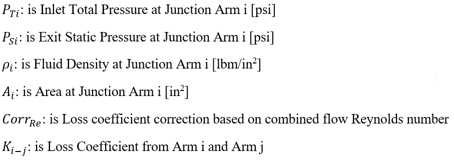
Nomenclature
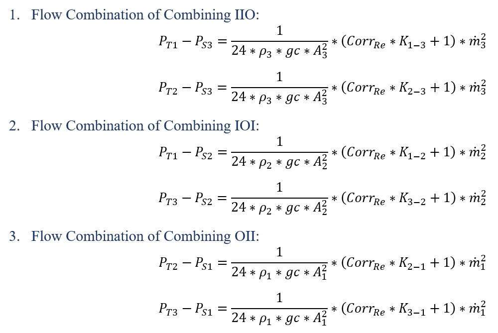
Junction Element Governing Equations
T-Junction and Y-Junction elements try to solve same set of momentum equations for a given flow configuration by enforcing continuity.
Junction Element Solution Method
The solution strategy of the junction solver is to utilize the Newton-Raphson method to solve the momentum equations in the residual equations form;
The Combining IIO configuration given in Table 1 can be written in the residual equation form [Eqn 2] and the 2x2 Jacobian matrix [Eqn 3] corresponding to that configuration becomes
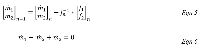
Flow rates are updated as given in [Eqn 5] until convergence is achieved, and
immediately after this, the continuity is enforced to calculate ![]() by [Eqn 6].
by [Eqn 6].
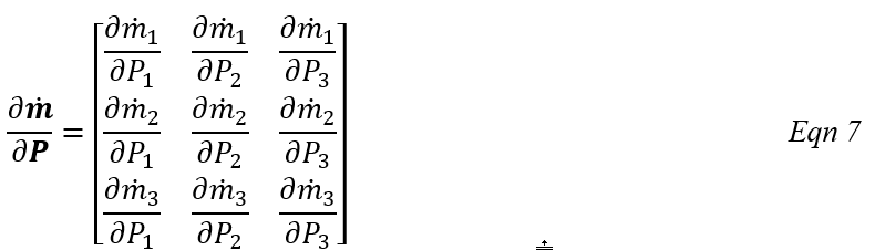
After junction solver is converged to a solution, next step is to calculate another set of derivatives for main solver. If an arm 𝑖 carries incoming flow, then 𝑃 is the total pressure at arm 𝑖. Conversely, if an arm 𝑖 carries exiting flow, then 𝑃 is the static pressure at arm 𝑖. In order to calculate flow derivatives, junction solver constructs a 3x3 matrix from momentum residual equations and continuity equation;
For example, for the flow configuration of Combining IIO, [Eqn 6] is added to
[Eqn 2]; ![]() and the new set of equations becomes:
and the new set of equations becomes:
![]()
And, the derivative of ![]() with respect to pressure
with respect to pressure ![]() can be written as
can be written as
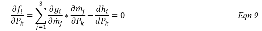
The linear system of equation using [Eqn 9] for residual equations j=1,2, and 3 will be
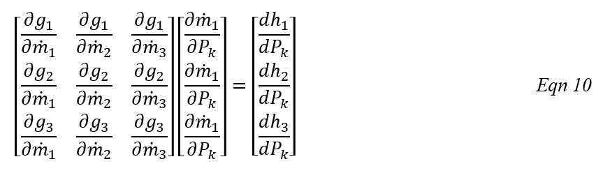
After solving [Eqn 10] for k = 1,2, and 3 junction element sends ![]() to main solver.
to main solver.
Junction Elements Outputs
Outputs in file with “res” extension. Output units controlled by user setting in “Output Control” panel.
| Name | Description | Units ENG, SI |
|---|---|---|
|
FLOWS: FLOW1: %W2 & MASSFLOWRATE FLOW2: %W2 & MASSFLOWRATE FLOW3: %W2 & MASSFLOWRATE |
Flow rates in %Wref and [PPS]or [kg/s] for all 3 Arms |
%Wref (None) (PPS, kg/s) |
| Associated Internal Chamber Data (for chamber specific output, please look at the Chambers Section) | ||
|
Flow Direction: IN or OUT |
IN: Element flow into the junction OUT: Element flow out of the junction |
(Node) |
| CHNUM |
Associated internal chamber ID. .1, .2, .3: Junction Arm IDs |
(None) |
| CHTYP | Associated internal chamber type | (None) |
| JUNCTION SOLVER STAT | ||
| JUNCTION_NEWTON_LOOP | Information about the convergence of Junction’s Newton method. | (None) |
| JUNCTION_NEWTON_ITER # | Iteration number at which the Junction’s Newton solver converged | (None) |
| MAX_RESIDUAL | Max residual during the run | (None) |
| USER_FLOW_CONFIG | User defined Flow Configuration | (None) |
| CALCULATED_FLOW_CONFIG |
Flow Configuration due to flow directions (This might differ from USER_FLOW_CONFIG). Flow Configurations: Lateral_Combining_IIO: T-Junction flow 3 is combination of flows 1 and 2 Lateral_Dividing_OOI: T-Junction flow 3 splits into flows 1 and 2 Lateral_Combining_IOI: T-Junction flow 2 is combination of flows 1 and 3 Lateral_Dividing_OIO: T-Junction flow 2 splits into flows 1 and 3 Lateral_Combining_OII: T-Junction flow 1 is combination of flows 2 and 3 Y_Dividing_IOO: Y-Junction flow 1 splits into flows 2 and 3 Y_Combining_IIO: Y-Junction flow 3 is combination of flows 1 and 2 Y_Dividing_OOI: Y-Junction flow 3 splits into flows 1 and 2 Y_Combining_IOI: Y-Junction flow 2 is combination of flows 1 and 3 Y_Dividing_OIO: Y-Junction flow 2 splits into flows 1 and 3 Y_Combining_OII: Y-Junction flow 1 is combination of flows 2 and 3 Y_Dividing_IOO: Y-Junction flow 1 splits into flows 2 and 3 Mom_Elm_Combining_IIO Mom_Elm_Dividing_OOI Mom_Elm_Combining_IOI Mom_Elm_Dividing_OIO Mom_Elm_Combining_OII Mom_Elm_Dividing_IOO Invalid (III or OOO) |
(None) |
| USER INPUT OPTIONS | ||
| SUBTYPE |
Subtype of the Junction element: T_JUNCTION Y_JUNCTION MOM_ELEM |
(None) |
| FLUID_MODE |
Fluid mode names: COMPRESSIBLE_GAS INCOMPRESSIBLE_GAS INCOMPRESSIBLE_LIQUID |
(None) |
| LOSS_METHOD |
Loss calculation method: INTERPOLATE_BTE_TABLES USE_TABLES_WITH_NEAREST_ANGLE USE_PREDIFINED_TABLES |
(None) |
| LOW_RE_CORR |
Low Reynolds number correction method: CORRECTION_TABLE_NOT_SET USER_DEFN_CORRECTION_DATA LOW_RE_CORR_MILLER_FIG_14p32_KTUR_0.5 LOW_RE_CORR_MILLER_FIG_14p32_KTUR_1 LOW_RE_CORR_MILLER_FIG_14p32_KTUR_5 LOW_RE_CORR_MILLER_FIG_14p32_KTUR_10 |
(None) |
| FLOW ORIENTATION | ||
| THETA | Tangential angles for the three junction arms | deg |
| PHI | Radial angles for the three junction arms | deg |
| RELANGLE | Relative inlet angle | deg |
| JUNCTION GEOMETRY | ||
| ANGLE | Angle between Arm 1 & 2 of the junction | deg |
| MINOR DIAMETER |
Diameter of the branch flow leg for T-Junction Diameter of the minor (divided) flow leg for Y-Junction Diameter of the downstream (Arm 2) of Momentum Element |
inch, m |
| MAJOR DIAMETER |
Diameter of the straight-through-pipe flow legs for T-Junction Diameter of the principal (combined) flow leg for Y-Junction Diameter of the upstream (Arm 1) of Momentum Element |
inch, m |
| LOSS RESULTS | ||
| Kij & Loss Source | K-Loss for Junction arms; i: inlet and j: outlet & which source is used to calculate K-Loss | (None) |
| RE_CORR_MULT | Multiplier for Reynolds number correction | (None) |
| HIGH_RE_MULT | Multiplier for Reynolds number correction | (None) |
| KTOTALij | Total K-Loss for Junction arms; i: inlet and j: outlet | (None) |
| CD | CD of Momentum Loss element | (None) |
| COEFF_PRESS | (None) | |
| ELEMENT RESULTS | ||
| FLOW RATE | Mass flow rates through Junction Arms 1, 2, & 3; (-) inflow, (+) outflow | pps, kg/s |
| PT | Total pressure of the associated internal chamber at each junction arm | psi, MPa |
| PS | Static pressure of the associated internal chamber at each junction arm | psi, MPa |
| TT | Total temperature of the associated internal chamber at each junction arm | degF, K |
| VEL | Velocity at the junction arm exit; (-) inflow, (+) outflow | ft/s, m/s |
| MACH | Mach number at the junction arm exit | (None) |
| REYN | Reynolds number at the junction arm exit | (None) |
| MATERIAL PROPERTIES | ||
| RHO | Density of the fluid at the Junction Arm 1, 2, & 3 | Lbm/ft3, kg/m3 |
| FS | Steam fraction | |
| CP | Specific Heat of the fluid at the Junction Arm 1, 2, & 3 at the latest total temperature | B/LbmDegF, J/kg/K |
| MU | Viscosity of the fluid at the Junction Arm 1, 2, & 3 at the latest total temperature | Lbm/HrFt, kg/m/s |
| GAM | Specific heat ratio of the fluid at the Junction Arm 1, 2, & 3 | (None) |
| RGAS | Gas constant at total pressure and temperature at Junction Arms 1, 2 & 3 | ft-lbf/lbm-R, J/kg/K |
References
Blevins, R. D. (2003). Applied Fluid Dynamics Handbook. Krieger Publications.
Kreyszig, E. (1999). Advanced Engineering Mathematics, 8th Ed. John Wiley & Sons.
Miller, D. (1990). Internal Flow Systems - Miller Innovations.