WSeal Element
WSeal Element General Description & Quick Guide

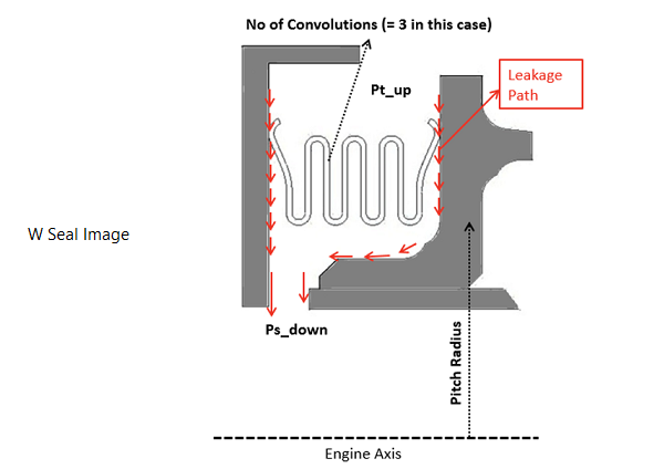
FlowSimulator W Seal element models the leakage flow across the W-Seal. This can be used only in Compressible (e.g. gas systems) analysis.
WSeal Element Inputs
Table of the inputs for the WSeal Element.
| Element Specific W Seal Input Variables | ||
|---|---|---|
| Index | UI Name (. flo label) | Description |
| 1 | No. of. Convolutions (NOC) | Number of Convolutions |
| 2 | Youngs Modulus | Youngs Modulus of WSeal Material |
| 3 | Pitch Radius | Pitch Radius measured from Engine centerline |
| 4 | Initial Compression | Initial Compression |
| 5 | Compression Model |
|
| 6 | Load (Deflection Based) | Load Acting on WSeal (Needed only when Compression model == ON) |
WSeal Element Theory Manual
| Nomenclature: | |
| : Mass flow rate | Specific heat Ratio |
| Tt: Total Temperature | R: Gas Constant |
| Pt: Total pressure | Ts: Static Temperature |
| Ps: Static pressure | Density |
| gc: Gravitational Constant | |
| Subscripts: | |
| in: Upstream station | ex: Downstream station |
W seal element solves the flow rate based on cross-sectional area and losses provided from user input.
If Compression if off, then
If Compression is on, then the calculated compression is based on number of convolutions
| Number of Convolutions | K_emp Calculations |
| 1 | |
| 2 | |
| 3 | |
| 4 |
![]()
![]()
Now the effective Clearance is computed by the following formula
![]()
![]()
Mass flow rate is calculated by Flow Function equation,
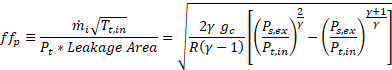
For Choked Condition
![]()
WSeal Element Outputs
The following listing provides details about WSeal Element output variables.
| Element Specific W Seal Output Variables | |||
|---|---|---|---|
| Index | Field | Description | Units |
| 1 | No.of. Convolutions | Number of Convolutions (User Input) | Unitless |
| 2 | Youngs Modulus | Youngs Modulus of WSeal Material (User Input) | Psi, mPa |
| 3 | Pitch Radius | Pitch Radius measured from Engine centerline (User Input) | in, m |
| 4 | Initial Compression | Initial Compression (User Input) | Unitless |
| 5 | Compression Model |
(User Input) |
|
| 6 | Load (Deflection Based) | Load Acting on WSeal (Needed only when Compression model= ON) (User Input) | lbf, N |
| 7 | Flow Regime | If Chocked flow | |
| 8 | Calc Compression | Calculated Compression if Compression model = ON | in, m |
| 9 | Total Compression | Initial Compression + Calc Compression | in, m |
| 10 | Effective Clearance | Clearance computed | in, m |
| 11 | Leakage Area | Leakage Area | in2 , m2 |
| 12 | Leakage Flow | Mass flow rate | Lbm/s, kg/s |
| 13 | VEX | Exit Velocity | ft/s, m/s |
| 14 | MACHEX (EXMN) | Exit Mach number | Unitless |
| 15 | PTS | Total Pressure Upstream | psi, mPa |
| 16 | PSEB | Static Pressure Downstream | psi, mPa |
| 17 | PTEX | Total Pressure Downstream | psi, mPa |
| 18 | TTS | Total Temperature Upstream | F, K |
| 19 | TTEX | Total Temperature Downstream | F, K |
| 20 | RHO | Density | lb/in3, kg/m3 |
| 21 | Gamma | Gamma | Unitless |
References
- Neelesh, S., Wolfe, C., Sezer, I., Ziegler, R., Chupp, R., “Chaterterization of metallic W-seals for inner to outer shroud sealing in industrial gas turbines”, Proc. ASME Turbo Expo 2012, GT2012-68131.
- Neelesh, S., “ Characterization of Metallic W Seals for Inner Shroud to Outer Shroud Sealing”, GRC-TISCAT report - 2010GRC861.
- Farahani, A., Childs, P., “Nozzle guide vane static strip seals”, Proc. ASME Turbo Expo 2006, GT2006-90185.
- Farahani A., Childs, P., “Characterization of static strip Seal flow”, Proc. ASME Turbo Expo 2007, GT2007-27469.
- Farahani, A., Childs, P., “Validation and comparison of strip seal design for gas turbine engine nozzle guide vanes”, Proc. 2008 ASME IMECE2008-68311.
- Ludwig, L., P., Johnson, R., L., “Sealing technology of aircraft gas turbine engines”, NASA Technical Memorandum -TM X-71607.
- “Seal Technology in Gas Turbine Engines”, AGARD Conference Proc – 237.
- Steinetz, M., Bruce, “Seal Technology”, Mechanical Engineers handbook – Materials and Mechanical design, Volume 1, Third Edition.
- Bill, C., Robert, “Wear of Seal Materials used in Aircraft Propulsion Systems”, Wear, 59 (1980) 168-189.
- http://www.nicholsons.com/pdf/E-Seals.pdf, Nicholsons Seals.
- http:/www.eaton.com/ecm , “Resilient Seals”, EATON’S Aerospace, TF100-35C_Resilient Seals.