Thermal Network
Thermal Network General Description
Thermal network entities are typically used to model;
- heat flow through solids, liquids or gases,
- heat flow from a surface to another surface via electromagnetic waves
- heat flow applied directly at a point
Flow Simulator enables to integrate thermal resistances of conduction, convection and radiation, and direct heat application either as a standalone network or as a thermal network coupled with flow network to generate combined results. Moreover, Steady-State and Transient analyses are available for both options.
The flow solver and thermal network solver are segregated: The thermal network and flow network carry out their runs separately and reach convergence independently of each other. They both must reach convergence for the run to complete successfully.
Quick Guide for Thermal Network Model Creation in the GUI
Flow Simulator allows users either to couple one (or more) Thermal Network with their Flow Network, or to model standalone Thermal Networks. The Thermal Network Section is placed after the Flow Section in the Element Library. Moreover, all the Thermal Network elements used in the models are listed in Thermal Model Browser.
A Standalone Thermal Network Model
In the standalone thermal network models, the thermal network elements are segregated from any flow elements. Simply, place boundary and internal nodes and then connect resistors (Conductor, Convector, Radiator and Heat Flow elements) to thermal nodes. The figure shows all the Thermal Nodes and Resistors connected to each other.
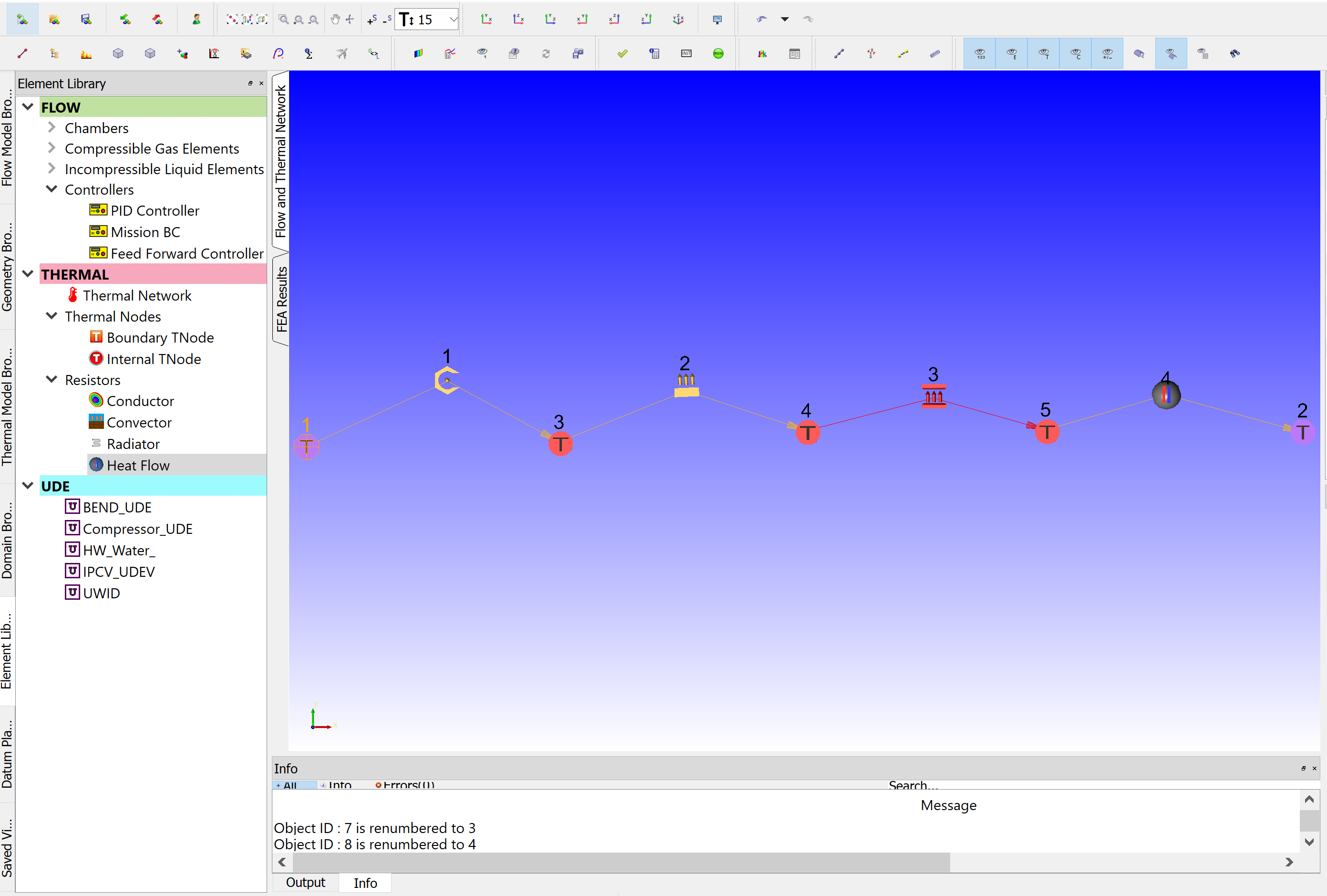
Figure: Standalone Thermal Network Example
“Node Temperature” must be set for all Boundary Temperature nodes. Currently, Flow Simulator does not have an initialization for the thermal network, thus “Node Temperature” as an initial guess must be defined for Internal Temperature Nodes in the Property Editor as well. And, if there exists a constant Heat input at the Internal Boundary location, this should be given as “Nodal Heat” input.
All the entities in the Property Editor should be filled for all used resistors:
There exist 2 subtypes of “Conductor” resistor. The conductivity can either be fixed value or be selected from the enabled materials, and Flow Simulator uses conductivity of that material. The geometric inputs of Cross-Section Area and Thickness for Simple Conductor and Inner – Outer Radiuses and Length of the Radial Conductor can be given as value or can automatically be obtained by selecting Tnodes or by measuring from GUI view.
The “Convector” element requires 2 inputs. If the Convector element is not associated with a Flow Element, then the only enabled HTC Relation is the Fixed HTC and its value should be given. The second input is Surface Area.
The “Radiator” resistor has 2 subtypes. Simple Radiation, which calculates the heat transfer on a single surface due to radiation, requires 3 inputs: Surface Area, Emissivity, and View Factor LR. However, when the radiation occurs between 2 parallel surfaces, “Radiation Between two Surfaces” subtype should be selected, and parameters of Surface Area and Emissivity should be given for both surfaces. The View Factor is given based on the View Factor Option. If the View Factor is from Left-to-Right then View Factor LR should be given, and View Factor RL should be filled if vice a versa.
The Heat Flow resistor must be positioned before or after a Boundary Temperature node, since, for internal heat addition, the Internal Tnode will be added with an input Q option as “Nodal Heat”. Surface Area and Heat Input should be set in the Property Editor for the Heat Flow resistor.
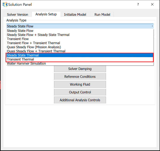
Figure: Solver > Analysis Setup > Analysis Type Selection for a Standalone Thermal Network
Once a Standalone Thermal Network has generated, the Analysis Type options are:
- “Steady State Thermal” for steady analysis
- “Transient Thermal” for transient analysis.
If needed, thermal network convergence tolerance and damping factors can be adjusted from Solvers Convergence and Damping Controls panels respectively.
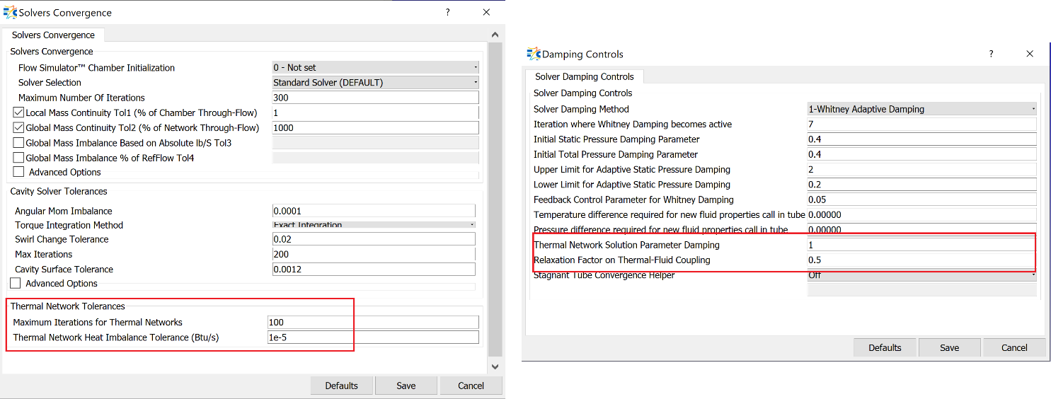
Figure: Thermal Network Tolerances and Damping Factors
Thermal Networks Combined with the Flow Network
There are 2 possible ways to combine a thermal network with a flow network.
Thermal Networks Coupled with the Flow Network
For the plain models, the thermal network can be coupled to a flow network on the same GUI view.
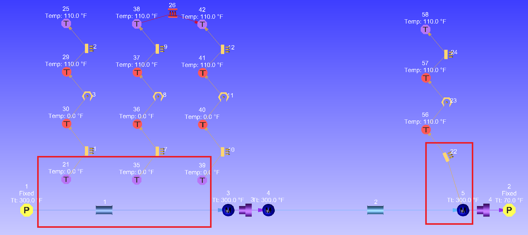
Figure: Thermal Network coupled with Flow Network
In the above example, the Boundary Temperature Nodes are associated with the Tube element and each Convector Resistor is linked to one of the tube segments. And the Convector Resistor is coupled with a Momentum Chamber.
When a Boundary Temperature Node is associated with an element, the temperature of the Boundary Tnode will be equivalent to the temperature of the fluid. Then, the associated Element ID and the element’s Axial Segment should be defined.
If the Convector resistor is coupled to an element, there are 2 ways to define heat transfer. The first way is to “Use Element Heat Transfer Setting”, in which the heat transfer calculations will be done based on the element’s settings. The second way is to set it to a fixed value or select one of the enabled HTC relations.
Note: the HTC calculation methods are different for coupling with an element then coupling with a chamber.
All other resistors are constructed as stated in the previous section.
Once the model construction completed, the Analysis Type can be selected as
- Steady State Flow + Steady State Thermal
- Transient Flow + Transient Thermal
- Quasi-Steady Flow + Transient Thermal (If the flow model does not have transient components such as tanks or accumulators this option can be used)
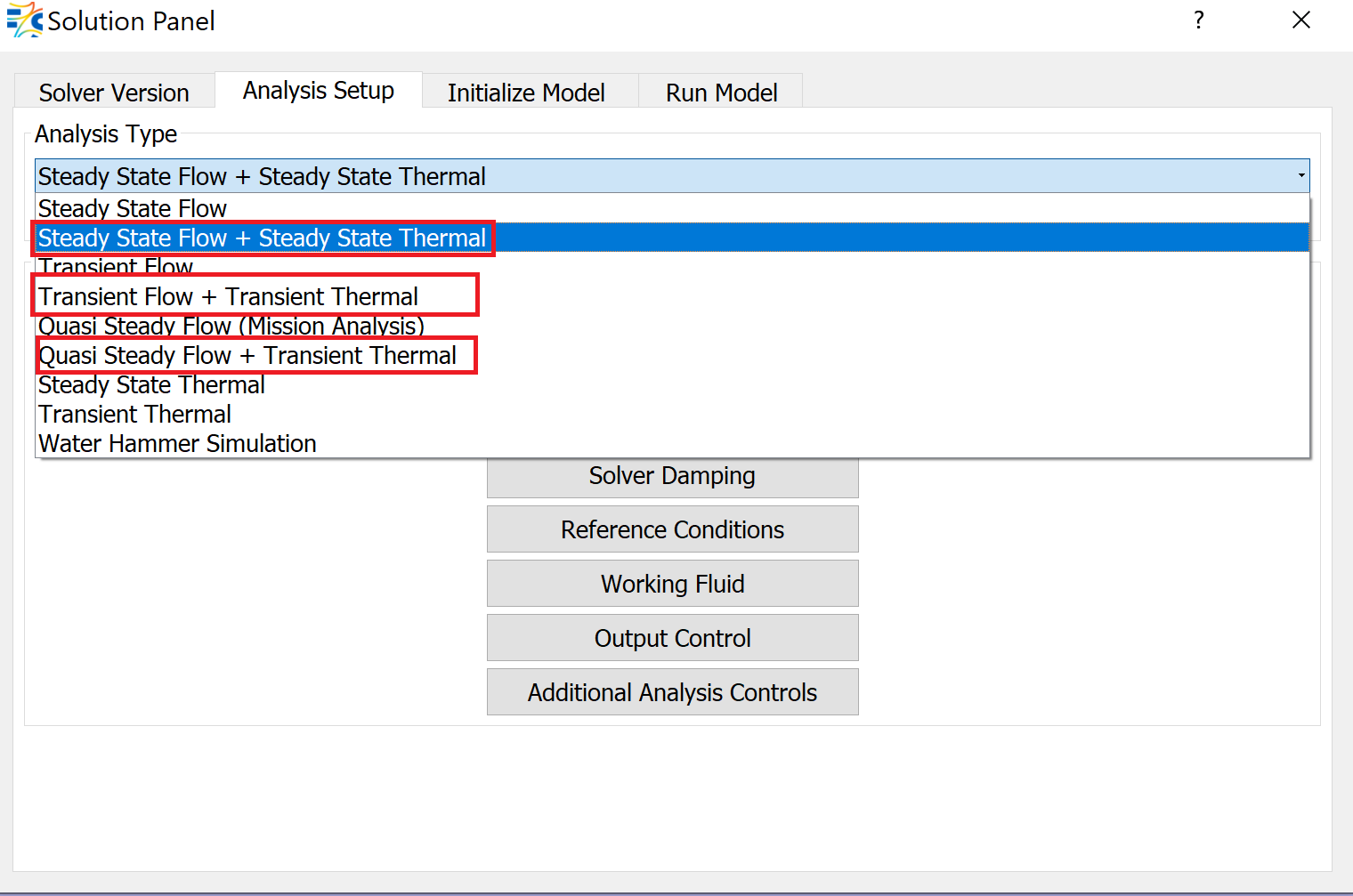
Figure: Analysis Type Selection for Thermal Network coupled with Flow Network Models
Thermal Networks Attached to the Flow Network
If both thermal network and flow network consist of many resistors and elements, respectively, it is also possible to attach thermal networks to flow network through TN Box. The TN box allows the user to group thermal items in an orderly fashion.
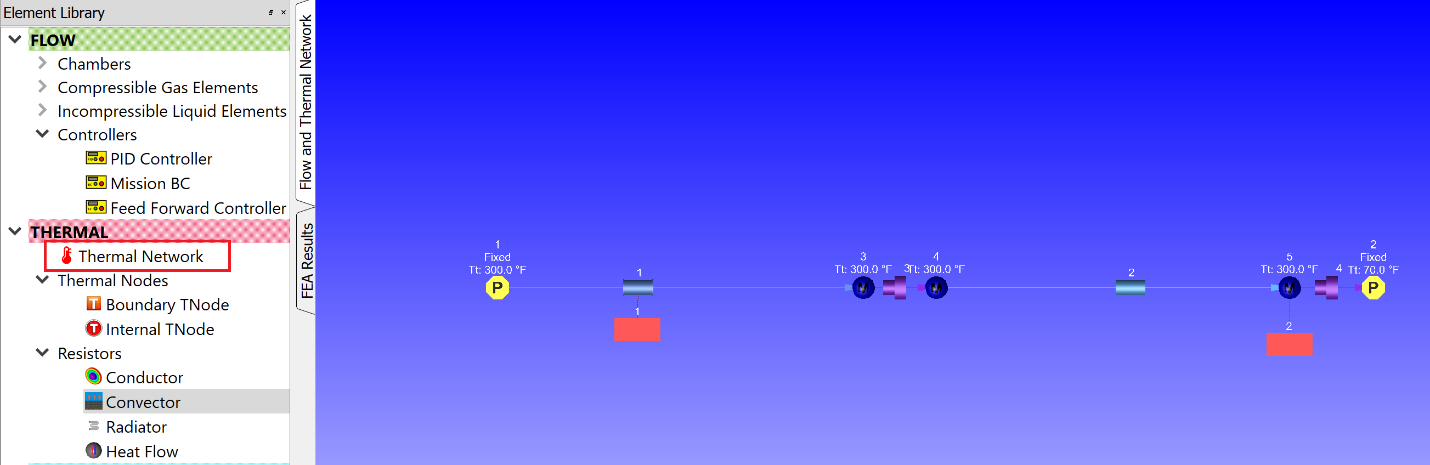
Figure: Thermal Network attached to Flow Network through TN Box
The TN Box is dragged and dropped in the model area near the element to which the thermal network is attached.
In order to attach the TN Box to the Flow Element or Chamber, first hold the Shift key and select the element or chamber with Left-Click, then keep holding down the Shift key, and Double-Click on the same element or chamber. Then the TN Box will relate to the target item with a dashed line.
The next step is to create the Thermal Network. Double-click on the TN box to get inside. By dragging and dropping thermal nodes and thermal resistor elements, the Thermal Network can be formed, and the procedure explained in the previous section can be followed.
Thermal Network Elements Input Variables
Thermal Node Input Variables
| Thermal Node Input Variables | ||
| Index | UI Name (. flo label) | Description |
| 1 | Type (TNODE_TYPE) | Type of a Thermal Node, it can be either Boundary or Internal |
| 2 | Associated with an Element (ASSOC_TYPE) | Type of a fluid entity with which the thermal node is associated. If the TNODE is not associated with a flow entity, then it takes NONE |
| 3 | Element ID (ASSOC_ID) | The identification number of the flow element that is associated with the Thermal Node. |
| 4 | Axial Segment ID (ASSOC_SEG) | If the associated element (Incompressible or Compressible TUBE or Advanced Orifice) has Stations, the parts between these stations are SEGMENTs. This variable defines which part of the element will communicate with the Thermal Node. |
| 5 | (ASSOC_SIDE) | If the associated element (Incompressible Tube or Advanced Orifice) has Wall Sides defined for the segments, then this variable specifies the wall side of the target segment of the target entity that the Tnode is associated with. |
| 6 | Node Temperature (TEMPERATURE) | Total temperature of the solid if the Tnode is not associated with flow entity. Otherwise, it is Fluid temperature, and should be set as FROM_FLUID. For the Internal TNODE, this value is an initial guess if it is not associated with Flow entity. |
| 7 | Volume (VOLUME) |
Volume of the internal temperature node. This variable used to calculate mass of the node only if the analysis is transient. NODE_MASS = NODE_VOLUME * RHO_NODE |
| 8 | Material List (MATERIAL) |
Material of the internal temperature node, and again, it is activated only at the transient analysis. The supported materials are:
|
| 9 | (COUPLING) |
This is type of data being transferred between the temperature node and the associated flow entity. There exist 5 inputs as a coupling method;
This is auto Generated Input. |
| 10 | Nodal Heat (NODAL_HEAT) | Constant heat input for the Internal Temperature Node |
Thermal Resistor Input Variables
Conductors
| Thermal Conductor Input Variables | ||
| Index | UI Name (. flo label) | Description |
| 1 | Not in UI (LEFT_NODE) | Identification number of Conductor resistor’s upstream Thermal Node. |
| 2 | Not in UI (RIGHT_NODE) | Identification number of Conductor resistor’s downstream Thermal Node. |
| 3 | Conductor Type (SUB_TYPE) |
Determines which subtype of a Conductor Resistor will be used:
|
| 4 | Material List (CONDUC/MAT) |
A fixed Conductivity [] value can be given or one of the supported material can be selected and Flow Simulator will determine the conductivity during the analysis.
|
| 5 | Cross-Section Area (SURFACE_AREA) | Conduction area |
| 6 | Thickness (THICKNESS) | Conduction length, i.e. the thickness of the conductor in the heat flow direction. |
| 7 | Inner Radius (INNER_RADIUS) | Inner Radius of the conductor |
| 8 | Outer Radius (OUTER_RADIUS) | Outer Radius of the conductor |
Convectors
| Thermal Conductor Input Variables | ||
| Index | UI Name (. flo label) | Description |
| 1 | Not in UI (LEFT_NODE) | Identification number of Conductor resistor’s upstream Thermal Node. |
| 2 | Not in UI (RIGHT_NODE) | Identification number of Conductor resistor’s downstream Thermal Node. |
| 3 | Use Element Heat Transfer Settings (HEAT_TRANSFER_FLAG) | When this option is selected, the flag becomes ‘FROM_FLUID’ and the heat transfer calculation will be done based on the associated element’s heat transfer settings. If this option is not selected, then the flag is NONE, and HTC_METHOD should be defined. |
| 4 | Surface Area (SURFACE AREA) | Surface area of the Convector |
| 5 | HTC Relation (HTC_METHOD) |
Specifies the Heat Transfer calculation method:
If the Convector resistor is coupled to an element:
If the Convector resistor is coupled to a chamber
|
| 6 | Heat Transfer Coefficient (HTC_VALUE) |
If HTC_METHOD is specified as FIXED_HTC, then its value should be set to HTC_VALUE. If either HEAT_TRANSFER_FLAG is set to FROM_FLUID or HTC_METHOD is set to one of the enabled HTC calculations method, then the HTC_VALUE becomes 0. |
| 7 | Turbulent HT Inlet Effects (HT_INLET_EFF) |
Heat Transfer inlet effect
Note: Turbulent HT Inlet Effects are available only for some of the HTC Relations ( Lapides-Goldstein, Dittus-Boelter, Sieder-Tate, Gnielinski, Bhatti-Shah) |
| 8 | Laminar HTC relation (LAMINAR_NUSSELT) |
Laminar HTC relation
Note: Laminar HTC Relations are available only for some of the HTC Relations (Lapides-Goldstein, Dittus-Boelter, Sieder-Tate, Gnielinski, Bhatti-Shah) |
| 9 | Subtype (SUBTYPE) |
For Plate in X-Flow, Turb., Avg (Colburn), Plate in X-Flow, Turb., Local (Colburn), Cylinder in X-Flow, Turb., Avg (Churchill-Bernstein)
For Hor. Plate in Free Conv., Turb., Avg.
|
| 10 | (LENGTH_SCALE) |
For Plate in X-Flow, Turb., Avg (Colburn), Plate in X-Flow, Turb., Local (Colburn)
For Cylinder in X-Flow, Turb., Avg (Churchill-Bernstein) and Hor. Cylinder in free Convection., Turb., Avg. (Churchill-Chu)
For Vert. Prism in Free Conv., Turb., Avg. (McAdams), Hor. Plate in Free Conv., Turb., Avg.
|
| 11 |
Cross Velocity |
For Plate in X-Flow, Turb., Avg (Colburn), Plate in X-Flow, Turb., Local (Colburn), Cylinder in X-Flow, Turb., Avg (Churchill-Bernstein)
|
| 12 | Tangential Angle |
For Plate in X-Flow, Turb., Avg (Colburn), Plate in X-Flow, Turb., Local (Colburn), Cylinder in X-Flow, Turb., Avg (Churchill-Bernstein)
|
| 13 | Radial Angle |
For Plate in X-Flow, Turb., Avg (Colburn), Plate in X-Flow, Turb., Local (Colburn), Cylinder in X-Flow, Turb., Avg (Churchill-Bernstein)
|
Radiators
| Thermal Conductor Input Variables | ||
| Index | UI Name (. flo label) | Description |
| 1 | Not in UI (LEFT_NODE) | Identification number of Conductor resistor’s upstream Thermal Node. |
| 2 | Not in UI (RIGHT_NODE) | Identification number of Conductor resistor’s downstream Thermal Node. |
| 3 | Radiator Type (SUB_TYPE) |
Determines which subtype of a Radiator Resistor will be used:
|
| 4 | Surface Area (Left) (SURFACE_AREA_L) | Surface Area of the left surface |
| 5 | Surface Area (Right) (SURFACE_AREA_R) | Surface Area of the right surface |
| 6 | Emissivity (Left) (EMISS_L) | Emissivity of the left surface |
| 7 | Emissivity (Right) (EMISS_R) | Emissivity of the right surface |
| 8 | View Factor (VIEW_FAC) | Radiation view factor, the portion of the radiation which leaves the left surface (or surface 1) and hits the right surface (or surface 2). View factor is based on line-of-sight, orientation, and distance between the two surfaces. |
Heat Flows
| Thermal Conductor Input Variables | ||
| Index | UI Name (. flo label) | Description |
| 1 | Not in UI (LEFT_NODE) | Identification number of Conductor resistor’s upstream Thermal Node. |
| 2 | Not in UI (RIGHT_NODE) | Identification number of Conductor resistor’s downstream Thermal Node. |
| 3 | Heat Flow into Node (Q_INPUT) | Constant heat value added on the surface |
| 4 | Surface Area (SURFACE_AREA) | Surface area |
Thermal Network Theory
Flow Simulator enables to model a standalone thermal network or couple thermal networks to flow network. Flow Simulator’s steady thermal solver has two assumptions:
- Heat (Q) can be along heat resistors (branches)
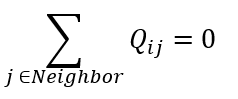
- Heat (Q) is balanced at user defined temperature nodes (TNodes)
Therefore, at a temperature node I, energy balance is written as
Flow Simulator includes four types of thermal resistors:
- Conductors
- Simple Conductor
- Radial Conductor
- Convectors
- Radiators
- Simple Radiator
- Two Surface Radiation
- Heat Flow
Thermal Resistors and Heat Flow Equations
Conductors
- Simple Conductor: Heat is carried from Left Node to
Right Node and regardless of the actual heat flow direction, (positive or
negative) is carried from Left to Right.
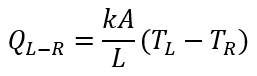
Where:
k: Conductivity
A: Surface Area
L: Thickness
- Radial Conductor: Heat is carried from Left Node to Right Node
along a radial conductor.
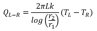
Where:
r2: Outer Radius
r1: Inner Radius
Convector
Heat flows from Left Node to Right Node along a convector.
![]()
Where:
h: Heat transfer coefficient (can either be fixed or based on a correlations). Refer Solver General theory sections for Heat Transfer Correlations.
A: Surface area
Radiators
- Simple Radiator: Heat is carried from Left Node to Right Node
through a simple radiator.
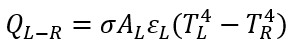
Where:
σ: Stefan-Boltzmann constant
 : Emissivity of Left
Surface
: Emissivity of Left
SurfaceAL: Left Surface’s Area
- Two Surface Radiation:Heat is carried from Left Surface to
Right Surface.
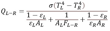
Where:
FL-R: View Factor
Heat Flow
User inserted Heat is carried from Left Node to Right Node. Since the Heat Flow resistor provides a constant heat flow, the derivatives are always zero.
![]()
Where:
Q: user inserted heat
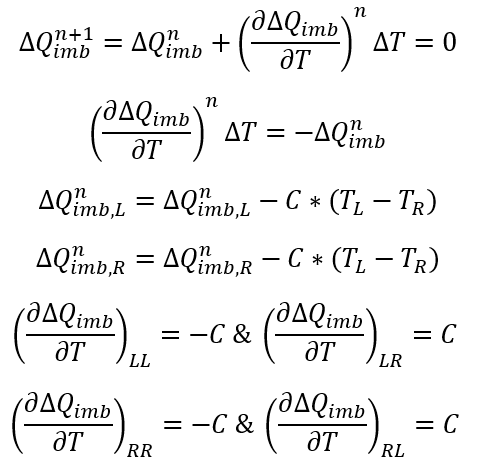
Numerical Method
At a Node I, the energy imbalance can be defined as:
![]()
And we try to obtain:
![]()
Therefore, the Newton’s method can be employed as
Jacobian Matrices
2D Jacobian Matrix for Linear Solver
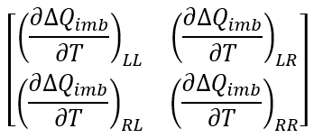
The Jacobian matrix used in Newton’s method is formed by looping over all heat resistors and the residual vector is obtained for free. It’s assumed that heat is flowing from Left node to Right node. The Jacobian matrix for each type of resistor has the form:
1D Jacobian Matrix for Sparse Solver
As the 2D Jacobian matrix requires Tnodes*Tnodes memory allocation, Linear Solver becomes inadequate for larger models. Thus, 1D coefficient matrix is formed again by looping all heat resistors, and sparse matrix is obtained by using the coordinate storage format.
Thermal Network Elements Outputs
Outputs in file with “res” extension. Output units controlled by user setting in “Output Control” panel.
| Name | Description | Units ENG, SI |
|---|---|---|
| THERMAL_NETWORK | More than one Thermal Networks can be constructed in one model; thus, this variable specifies the Thermal Network’s identification number. | None |
| WITH ASSOC_ITEMS | If the Thermal Network is coupled with Flow Network, the associated Flow entities are listed with this variable. Exx represents Elements, and Cxx represents Chambers. | None |
| SIMULATION | The Analysis type (either STEADY-STATE or TRANSIENT) is stated with this parameter. | None |
| MATRIX SOLVER | The Jacobian matrix can be solved either by Linear Solver or by Sparse Solver. | None |
| NUM_STREAMS | Number of fluid streams in the thermal network, taken from associated fluid network item | None |
| NUM_TNODES | Number of Active Thermal Nodes (Boundary TNode and Internal TNode) | None |
| NUM_CONDUCT | Number of Active Conductors | None |
| NUM_CONVECT | Number of Active Convectors | None |
| NUM_RADIAT | Number of Active Radiators | None |
| NUM_HEAT_FLOW | Number of Active Heat Flows | None |
| CONVERGE INFO | Line of text that gives convergence information for the thermal network. Gives the number of thermal iterations model took to converge, which fluid network (MAIN SOLVER) iteration the thermal network ran on and the root-mean-square error of the thermal network solution | None |
| Thermal Node Results | ||
| TNODE | Thermal node number | None |
| TYPE | Type of Thermal Node; Boundary Tnode (B) or Internal Tnode (I) | None |
| COUPLING |
Information about the associated flow item
|
None |
| QIMBALANCE | Heat (Q) imbalance at the thermal node | Btu/s, W |
| TT | Total Temperature of the Thermal Node | Deg F, Deg K |
| CAPACITANCE | Thermal capacitance of the Thermal Node material | Btu/DegF, J/Deg K |
| DENSITY | Density of the Thermal Node material | Lbm/ft3, kg/ft3 |
| CP | Specific heat of the Thermal Node material | Btu/lbm-Deg F, J/kg-Deg K |
| NODAL_HEAT | Heat addition or removal from the Thermal Node | Btu/s, W |
| Resistor Results | ||
| IDNUM | Identification number of the resistor | None |
| TYPE |
Type of the resistor:
|
None |
| SUBTYPE |
Subtype of the resistors:
|
None |
| HEAT_FLOW | Heat flow across the resistor | Btu/s, W |
| CONDUCTANCE | Conductance of the resistor | Btu/s/Deg F, W/Deg K |
| LNODE | Identification number of the resistor’s left-side node | None |
| LCOUPLING | Information about coupling of the left node. Follows same scheme as COUPLING in the Thermal Node Results table (see above), except that the LCOUPLING line will start with either B for a boundary thermal node or I for an internal thermal node | None |
| L_TT | Total temperature of the Left Thermal Node | Deg F, Deg K |
| RNODE | Identification number of the resistor’s right-side node | None |
| RCOUPLING | Information about coupling of the right node. Follows same scheme as COUPLING in the Thermal Node Results table (see above), except that the LCOUPLING line will start with either B for a boundary thermal node or I for an internal thermal node | None |
| R_TT | Total temperature of the right Thermal Node | Deg F, Deg K |
| HTC | Heat transfer coefficient calculated for the Convector resistor | B/HrFt2F, W/m2/K |
| COND | Conductivity through the Conductor resistor | B/HrFt degF, W/m/Deg K |
| EMIS1 | Emissivity of the left node surface (Radiator resistor only) | None |
| EMIS2 | Emissivity of the right node surface (Radiator resistor only) | None |
References
- Chapman, A. J. (n.d.). Fundamentals of Heat Transfer. 1987: Macmillan.
- Churchill, S. a. (1977). A Correlating Equation for Forced Convection From Gases and Liquids to a Circular Cylinder in Crossflow. J. Heat Transfer, 300-306.
- Churchill, S. W. (1975). averaged Nusselt number for turbulent free convection around a. Int. J. Heat Mass Transfer, 1049.
- Holman, J. P. (n.d.). Heat Transfer (8th ed.).
- Incropera F.P., D. D. (n.d.). Fundamentals of Heat and Mass Transfer", 7th edition Eq. 8.62.
- Incropera, F. a. (2006). Fundamentals of Heat and Mass Transfer, 6th Edition. John Wiley & Sons.
- Kreith, F. a. (1980). Basic Heat Transfer.
- Lapides, M. a. (1957). HEAT TRANSFER SOURCE FILE DATA. APEX 425 United States.
- M.E.Crawford, W. a. (1976). Convective Heat and Mass Transfer.
- R.K.Shah, M. a. (1987). Turbulent and transition flow convective heat transfer in ducts, in Handbook of Single-Phase Convective Heat Transfer Chapter 4.
- Weise, S. (n.d.). Average turbulent Nu on short, vertical planes and cylinders, Heat Transmission, Third Edition. McAdams.