Chambers
Chamber General Description & Quick Guide
In FlowSimulator, chambers represent regions of essentially constant fluid properties including flow velocity and vector direction. They serve as connection points for the FlowSimulator elements. Each chamber collects flow from all elements entering that chamber and discharges flow to all elements leaving that chamber. Nominally the elements having the chamber designated as the "downstream chamber" supply the entering flow and the elements having the chamber designated as the "upstream chamber" receive the flow leaving the chamber. However, it is possible that these roles will change as the direction of flow in some elements may reverse when FlowSimulator balances out the chamber pressures during the iterations. FlowSimulator permits no mass flow accumulation in chambers. Hence only steady state analysis is possible, and a perfect flow balance requires,
![]()
Each of the available chamber types will be described below.
Chamber Types
There are three main types of chambers in FlowSimulator: the plenum, the momentum balance, and the inertial chamber. There is also a vortex chamber which is only used to store data for vortex segments. There are additional sub types of Momentum chamber exist, Elevation Chamber (Account for Potential Height Change)
Plenum Chamber
The plenum chamber is used to model a region in which there is no significant velocity head present. In this case any velocity head of flow entering the chamber is dissipated and the total pressure in the chamber is equal to the static pressure. The plenum chamber is assumed to be rotating at the same speed as all of its attached elements. Therefore, all of its attached elements must be rotating at the same speed (or all elements can be stationary).
Momentum Chamber
In the momentum balance chamber, the mixed total pressure head of all flows entering the chamber is computed and resolved to give a vector flow direction. In this calculation, the direction of each incoming stream is defined by the element angles specified for the element from which the flow enters. Thereafter, according to the angular alignment of an element with flow leaving the chamber with this chamber flow direction, the appropriate component of total pressure in the direction of the element is used to drive flow from the chamber into the element. For nonrotating components, selection of the coordinate system directions relative to the engine axis is arbitrary where momentum chambers are concerned since it is only relative angle between elements that determines the inlet component of total pressure to each element. For rotating components, the coordinate system direction is not arbitrary. The same θ and ϕ angle convention as used for inertial chambers should be used so correct swirl velocities are calculated. However, it is advisable to only use momentum chambers when the swirl velocity is 0 (stationary components such as piping) or when the swirl velocity is the same as the metal rotation (XK=1, air is “onboard” the rotor). The momentum chamber is assumed to be rotating at the same speed as all of its attached elements. Therefore, all of its attached elements must be rotating at the same speed (or all elements can be stationary). Caution must be used with momentum balance chambers since the computed mixed total momentum is only valid for the total exit area of the elements having flow entering a downstream chamber. FlowSimulator assumes that the momentum of the mixing flows does not dissipate even if the downstream element(s) have a larger flow area than this. Another way of looking at this is that FlowSimulator assumes a perfect diffuser if the combined flow area of the downstream element inlets is greater than the combined exit areas of the upstream elements.
Inertial Chamber
The inertial chamber is used to model the effects of tangentially swirling air or relative tangential velocity differences between air and a rotor. The flow direction coordinates for inertial chambers are three-dimensional and follow the convention, based on the definitions in the Coordinate System section, of Z as the axial direction, U as the tangential direction and R as the radial direction. The corresponding angles are Theta (θ) in the tangential direction and Phi (ϕ) in the radial direction. The inertial chamber must be used to connect elements rotating at different speeds.
Vortex Chamber
The vortex chamber was created to facilitate the new vortex element type. No elements can use a vortex chamber as the upstream or downstream chamber. A vortex chamber’s main use is store data (XK, P, T) at vortex segments and stations. A vortex chamber store temperature in the absolute frame like an inertial chamber. The chamber centric cavity modelling in FlowSimulator requires that a chamber be associated with each cavity. Only chambers in the absolute reference frame (inertial and vortex chambers) can be associated with a cavity.
Chamber Inputs
The following table provides a description of FlowSimulator chamber variables. The variables are listed in the order they appear as columns of the “Chamber Data” section of a FlowSimulator model database.
| CHAMBER INPUT VARIABLES | ||
|---|---|---|
| Index | UI Name (. flo label) | Description |
| 1 | none | A simple sequential index for the convenience of users looking at the file. |
| 2 | Chamber Number (CHNUM) |
Chamber identification number. The maximum permissible value is 9999. |
| 3 | Type (TYP) |
Chamber type. The TYP variable can be up to 3 characters. The presence of ‘-’ indicates the chamber is inactive. The presence of ‘B’ indicates the chamber is a boundary chamber. The final character indicates which type of chamber: plenum ‘P’, momentum ‘M’, inertial ‘I’, elevation ‘E’, or vortex ‘V’. Vortex chambers cannot serve as boundaries. Examples are: P, M, E, I, BP, BM, BE, BI, V, -P, -M, -E, -I, -V, -BP, -BM, -BI. |
| 4 | Calculate Temperature (TFIX) |
Identifies any internal (non-boundary) chamber that has a fixed (known) temperature. A value of 0 denotes a variable temperature (calculated by FlowSimulator), while a value of 1 denotes a permanently fixed chamber temperature.
If TFIX is greater than 1, the chamber temperature is held fixed for TFIX number of iterations. If the model has not already converged, the chamber temperature is allowed to vary (i.e. be calculated by FlowSimulator) thereafter.
The value of TFIX for boundary chambers is not used. |
| 5 | Relative Total Pressure (TOTPRES) |
Chamber total pressure For internal chambers, the TOTPRES input is used as an initial guess. For boundary chambers, TOTPRES is the boundary value. |
| 6 | Static Pressure (STATPRES) |
Chamber static pressure. For internal chambers, the STATPRES input is used as an initial guess. For boundary chambers, STATPRES is the boundary value. |
| 7 | Relative Total Temperature (TOTTEMP) |
Chamber fluid total temperature. For internal chambers, the TOTTEMP input is used as an initial guess unless the TFIX variable is non-zero. See the description of the TFIX variable for the interpretation of non-zero values of TFIX. |
| 8 | Mach Number (XMRES) |
Chamber fluid Mach number. If the chamber is a plenum chamber, then the XMRES input will be overwritten and set to 0. For internal chambers, the XMRES input is used as an initial guess. |
| 9 | Velocity Tangential Angle (THTARES) |
Chamber fluid Theta flow direction angle. If the chamber is a plenum chamber, the THTARES input will be overwritten and set to 0 since it is undefined when the fluid velocity is 0. For internal chambers, THTARES is used as an initial guess. |
| 10 | Velocity Radial Angle (PHIRES) |
Chamber fluid Phi flow direction angle. If the chamber is a plenum chamber, the PHIRES input will be overwritten and set to 0 since it is undefined when the fluid velocity is 0. For internal chambers, PHIRES is used as an initial guess. |
| 11 | Mass Ratio: Second Fluid to Total (FS) |
Chamber secondary fluid mass fraction (mass flow of fluid 2 over total mass flow). 0 ≤ FS ≤ 1 0: All fluid 1 1: All fluid 2 For internal chambers, FS is used as an initial guess. By default, fluid 1 is air and fluid 2 is steam and for the large majority of models, FS is 0 everywhere.
The FS input variable also allows the user to specify the fluid type as a liquid in FlowSimulator. Currently five liquid types are supported. The FS values for the supported liquid types are: 30:Liquid Water 31: Jet-A 32:MIL_PRF_23699 Oil 33: MIL-L-7808 Oil 35: VG-32 Oil
If Custom Materials are defined, the custom material component ID is used as FS value of Chambers. |
| 12 | For Forward Flow (CH_XK_FWD) |
Chamber fluid swirl factor (XK). Swirl factor is the ratio of the fluid absolute tangential velocity to the chamber’s reference tangential velocity.
For vortex chambers, this is the swirl value that is used when flow is in the forward direction through the vortex element.
For non-vortex chambers, this is the swirl value that is delivered to elements with this chamber as their upstream chamber when the element flow is in the forward direction. CH_XK_FWD is used as an initial guess if a cavity is attached to this chamber or if the XKFIX value is 0.
CH_XK_FWD takes precedence over the vortex element XK_FWD variable. |
| 13 | For Reversed Flow (CH_XK_REV) |
Chamber fluid swirl factor (XK). Swirl factor is the ratio of the fluid absolute tangential velocity to the chamber’s reference tangential velocity.
For vortex chambers, this is the swirl value that is used when flow is in the reverse direction through the vortex element.
For non-vortex chambers, this is the swirl value that is delivered to elements with this chamber as their user-defined downstream chamber when the element flow is reversed. CH_XK_REV is used as an initial guess if a cavity is attached to this chamber or if the XKFIX value is zero.
CH_XK_REV takes precedence over the vortex element XK_REV variable. |
| 14 | Chamber XK (XKFIX) |
Identifies any chamber that has fixed (known) CH_XK_FWD and CH_XK_REV values. Flag that identifies how to handle CH_XK_FWD and CH_XK_REV. 0: Allow FlowSimulator to update CH_XK_FWD and CH_XK_REV with the upstream element’s outbound fluid rotation or cavity solver swirl factors. 1: Maintain the user-initialized values for CH_XK_FWD and CH_XK_REV. If a cavity is attached to this chamber, XKFIX is always interpreted as 0 regardless of the user input. |
| 15 | Heat Added or Removed (CH_QIN) |
Specifies heat input at the chamber. Positive values indicate heat is added. Negative values indicate heat is being withdrawn. This heat addition or extraction is independent from cavity and element related heat. |
| 16 | Rotor Index (RTR_IDX) |
Points to the ELERPM value that is used as the reference rotation (for multiplying by CH_XK_FWD, CH_XK_REV, XK_FWD, and XK_REV).
For inertial and vortex chambers, the user choice of RTR_IDX is used. For plenum and momentum chambers, FlowSimulator corrects RTR_IDX to agree with neighbouring elements. The vortex RTR_IDX is also required to agree with the nearby chamber RTR_IDX values.
An error or warning will be issued in the convhis_fi.dat file when FlowSimulator detects a mismatch. |
| 17 | Height (HEIGHT) | Chamber Height used for Elevation Chamber subtype. |
Order of Precedence for Chamber Inputs
The following table lays out the methodology that FLOWSIMULATOR uses to establish the initial chamber properties based on the chamber type and user specified chamber inputs.
| ORDER | ACTION |
|---|---|
| 1 |
If user does not specify the chamber Mach number (MACH = 0.): Fluid swirl (CH_XK_FWD), radius (CH_RAD), and rotational speed (RTR_IDX) are used to calculate the chamber Mach number (MACH). (For plenum chambers, MACH = 0.) |
| 2 |
If user does not specify the chamber static pressure (STATPRES = 0.): Total pressure (TOTPRES) and Mach number (MACH) are used to determine the chamber static pressure (STATPRES) and resolved fluid velocity magnitude (VRES). (For plenum chambers, STATPRES = TOTPRES, MACH = 0, and VRES = 0.) |
| 3 |
If user does specify the chamber static pressure (STATPRES ≠ 0.): STATPRES and Mach number (MACH) are used to determine the chamber total pressure (TOTPRES) and resolved fluid velocity magnitude (VRES). (For plenum chambers, TOTPRES = STATPRES, MACH = 0, and VRES = 0.) |
Chamber Theory Manual
The state of a FLOWSIMULATOR chamber is represented by the following variables.
PTC(i): Total pressure
PSC(i): Static pressure
TTC(i): Total temperature
XMRES(i): Resultant Mach number
FS(i): Secondary fluid mass fraction
VRES(i): Magnitude of flow velocity
THRES(i): Tangential flow angle
PHRES(i): Radial flow angle
CPRES(i): Specific heat
GRES(i): Specific heat ratio
RRES(i): Gas constant
PTC, PSC, TTC, THRES, PHRES, XMRES and FS are the chamber variables contained in the FlowSimulator input files and printed in the FlowSimulator output files. By definition, the residual velocity is zero in a plenum chamber and the total pressure is equal to the static pressure. Non-zero flow angles specified in the input for plenum chambers are reset to zero by FlowSimulator. Beyond the possibility of non-equal total and static pressures in plenum chambers, other inconsistencies can exist in the input data for a chamber. FlowSimulator uses a hierarchy to resolve such conflicts. The static pressure, PSC, and Mach number, XMRES, are treated as the primary variables. Values of XMRES specified in the input file must not be negative and for plenum chambers they must be zero. Invalid values of XMRES will be set to zero. If PSC is not greater than zero and a value greater than zero is input for the total pressure, PTC, then total pressure will be used. Warning messages are printed to the conhist_fi.dat' file when chambers with inconsistent input data are found.
Recalculating the Chamber State
Fluid state in each chamber, with the exception of boundary chambers, is recalculated for each iteration as the solution progresses. The total and static pressure in the non-boundary chambers are the independent parameters varied by FlowSimulator to balance the flows in the circuit. The remaining chamber variables, other than those specified as fixed by some other input to the model, are dependent variables. To calculate the dependent chamber variables FlowSimulator employs the data of all the element flows entering the chamber.
For each element flow the following data is known,
W: Element flow rate
SFE: Secondary fluid mass fraction in element flow
JC: Downstream chamber number
NED: Number of element flows entering downstream chamber
TTE: Total temperature relative to the chamber rotational speed
XCP: Specific heat
PHEX: Radial flow angle relative to the chamber
THEX: Tangential flow angle relative to the chamber
VXE: Magnitude of flow velocity relative to the chamber rotational speed
(The value for XCP is obtained from the properties subroutine using TTE, SFE and the static pressure in the chamber (PSC))
The above data for each element with flow entering chamber is summed to give the following total values:
The dependent chamber values are then computed from these flow-weighted values. If a chamber has no inflow, none of the dependent chamber values are updated but their values from the previous iteration are retained for use. If there is inflow into a chamber, recalculation of the properties is done.
The secondary fluid mass fraction is simply the ratio of the secondary fluid flow into the chamber to the total inflow
The temperature of the chamber is computed as a flow and specific heat ratio weighted average. Since specific heat is itself temperature dependent, an average value between that represented by the sums calculated for the incoming flows and the specific heat of at the final mixed chamber temperature is used. This is accomplished by a simple three-loop iteration process. Initially TTOT is calculated as:
Following this two more passes are made using the equation
CPTOT is obtained from the property’s routine using the then current value of TTOT. To complete the calculation the temperature is calculated as
![]()
Once the temperature has been established the properties routine is called to establish new values for specific heat, CPRES(i), specific heat ratio, GRES(i) and gas constant, RRES(i). The computed values of the velocity and flow direction angles depend on the type of chamber as described in the following sections.
Velocity and Flow Angles in Plenum Chambers
Since
there is no velocity head associated with a plenum chamber, the values of Mach number,
resultant velocity, and flow angles are not updated but remain set at zero. Hence for
each plenum chamber (i) we have,
Velocity and Flow Angles in Momentum and Inertial Chambers
The momentum and inertial chambers, while used differently
during element flow calculations, are handled similarly when the chamber velocity and
flow angles are calculated. The tangential flow angle is computed from the axial and
tangential components of mixed total momentum,![]() The radial flow angle, which is measured in the
radial direction from the axial-tangential component of velocity, is computed from all
three components of mixed total momentum,
The radial flow angle, which is measured in the
radial direction from the axial-tangential component of velocity, is computed from all
three components of mixed total momentum,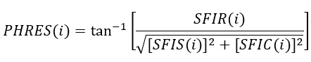 Likewise, the velocity is computed from the three
components of the mixed total momentum and the total flow rate,
Likewise, the velocity is computed from the three
components of the mixed total momentum and the total flow rate, 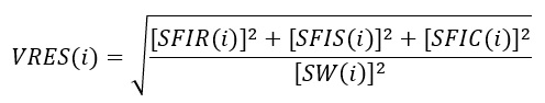 The resultant Mach number is computed from Mach
number routine using TTC, GRES, RRES and VRES.
The resultant Mach number is computed from Mach
number routine using TTC, GRES, RRES and VRES.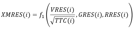
For inertial chambers, XMRES is not limited in magnitude and may be greater than 1.0 if VRES is sufficiently large. For momentum chambers, the GENDAT input variable ISUPER determines whether XMRES is permitted to be supersonic. The default value of ISUPER = 0 limits the maximum value of XMRES for momentum chambers to 1.0. The chamber XK (swirl ratio) is not a primary chamber variable but it is calculated in the same routine as the rest of the chamber data so will be described here. The calculated XK’s are calculated and reported with respect to the absolute reference frame for all chamber types. The XK calculation does depend on the chamber type, however. The XK of a plenum chamber should always be 0 or 1 since a plenum chamber is rotating with its attached elements and the through flow velocity from the attached elements is dissipated. The XK for a momentum chamber is based on the velocity in the chamber, VRES, the flow angles, θ and ϕ and the chamber rotation. The XK for an inertial chamber is based on the velocity in the chamber, VRES, the flow angles θ and ϕ. If the inertial chamber is associated with a cavity, the calculated cavity XK is used to set the chambers tangential velocity by recalculating SFIS.
Chamber Radius
The chamber radius, CH_RAD, is determined by the average radius of certain elements attached to the chamber. The elements used for averaging are the following: rotating tube, rotating orifice (Conventional, Effective Area Orifice, and CDComp), Vermes seal, and a vortex element. All element attached to a chamber should have the same radius, but if they do not a warning will be written. If the chamber is a vortex type chamber it will not have any attached elements. A Vortex chamber will get its radius from the average of the cavity surface radial extent (for vortex chambers with cavities) or from the vortex element stations.
Chamber XK
The chamber swirl ratio, CH_XK_FWD (for forward flow) and CH_XK_REV (for reverse flow), is also calculated for use in the cavity and vortex modules and output to the “.res” file. The swirl is relative to the user provided ELERPM(CHM_RTR_IDX). The chamber XK is always an absolute value (V_θ used in XK calculation is absolute).
Chamber Outputs
The following table provides a description of FlowSimulator chamber output variables. The variables are listed in the order they appear as columns ‘.res’ file.
| Name | Description | Units |
|---|---|---|
| CHAM | Chamber identification number. | (ID number) |
| (CH)TYP |
Chamber type. P: Plenum M: Momentum I: Inertial V: Vortex |
(flag) |
| ERROR1 | Flow imbalance at the chamber as a percentage of the total flow through the chamber. | (%) |
| PTC |
Chamber total pressure. Relative for plenum and momentum chambers. Absolute for inertial and vortex chambers. |
psi, mPa |
| PSC | Chamber static pressure. | psi, mPa |
| TTC |
Chamber total temperature. Relative for plenum and momentum chambers. Absolute for inertial and vortex chambers. |
deg F, K |
| THRES |
Resolved theta angle of flows entering the chamber. Relative for plenum and momentum chambers. Absolute for inertial and vortex chambers. |
deg |
| PHIRES |
Resolved phi angle of flows entering the chamber. Relative for plenum and momentum chambers. Absolute for inertial and vortex chambers. |
deg |
| MACH |
Resolved Mach number of flows entering the chamber. Relative for plenum and momentum chambers. Absolute for inertial and vortex chambers. |
(unitless) |
| FS | Secondary fluid mass fraction. | (unitless) |
| XK | Fluid rotation as a fraction of the chamber’s reference rotation. | (unitless) |
| RTR |
A pointer to the chamber’s reference rotation (RPM) for fluid rotation calculations. 0: Stationary. 1: ELERPM(1). 2: ELERPM(2). 3: ELERPM (3). |
(index) |
| T_FRM |
A pointer to the chamber’s reference rotation (RPM) for fluid temperature calculations. 0: Stationary. 1: ELERPM(1). 2: ELERPM(2). 3: ELERPM (3). -1: Rotating with the fluid from the upstream element. -2: Rotating with the fluid from the downstream element. |
(index) |
| CH_QIN |
Heat input to the chamber. Positive values indicate heat added to the fluid; negative values indicate heat removed. |
BTU/s, W |
| RAD | Central radius of the chamber. | inch, mm |
| TS | Chamber static temperature. | deg F, K |
| TT_ABS | Chamber absolute total temperature. | deg F, K |
| TT_REL | Chamber total temperature relative to the rotational reference frame (i.e. rotor). | deg F, K |
| TFIX |
Flag that tells how chamber temperature was fixed: 0: Variable temperature (calculated by FlowSimulator). 1: Permanently fixed chamber temperature. > 1: Chamber temperature is held fixed for TFIX number of iterations and, if the model has not already converged, the chamber temperature is allowed to vary (i.e. be calculated by FlowSimulator) thereafter. |
(flag) |
| VRES |
Resolved fluid velocity magnitude of flows entering the chamber. Relative for plenum and momentum chambers. Absolute for inertial and vortex chambers. |
ft/s, m/s |
| VAX | Component of chamber resolved velocity in the axial direction. | ft/s, m/s |
| VRAD | Component of chamber resolved velocity in the radial direction. | ft/s, m/s |
| VABS_TAN |
Absolute fluid tangential velocity. (For an inertial or vortex chamber, this will be the same as VRES_TAN.) |
ft/s, m/s |
| VREL_TAN |
Fluid tangential velocity relative to the rotational reference frame (i.e. rotor). (For a plenum or momentum chamber, this will be the same as VRES_TAN.) |
ft/s, m/s |
| VRES_TAN | Component of chamber resolved velocity in the tangential direction. | ft/s, m/s |
| CH_RPM | Reference rotational speed of the chamber (based on T_FRM). | rev/min |
| Height | Chamber Height | inch, mm |