General Overview
FlowSimulator Solver Overview
FlowSimulator is a computer program for the analysis of steady-state compressible & incompressible fluid flow, steady state thermal predictions, Transient Flow & Thermal Behaviour through networks of flow & thermal conduits. Having been created for use in the design of gas turbine engines, FlowSimulator includes the capability to treat flow in rotating and stationary reference frames, as well as transferring fluid between reference frames. The standard working fluid is air, while real gases, water, oil, and steam are available as alternate fluids. FlowSimulator makes provision for the analysis of mixtures of two gases. The available fluid composition options are air as a perfect gas, a mixture of air as a perfect gas with steam, a single real gas, a mixture of air as a perfect gas with one real gas, and a mixture of two real gases.
FlowSimulator networks consist of flow conduits known as “elements” connected between nodes known as “chambers.” The boundaries of the network are defined by "boundary chambers," which have fixed fluid properties, both thermodynamic and dynamic. Flow passes into and out of the network via boundary chambers. Various types of elements are available for use within a flow network. The selection of elements consists of orifices, tubes, valves, junctions, bends, transitions and seals, vortexes, and variations thereof. All element types have one upstream chamber and one downstream chamber.
Three in-network chamber types are available:
- the plenum chamber, which dissipates fluid velocity of incoming flows by fixing dynamic terms to zero;
- the momentum chamber, which computes the resultant chamber flow velocity (including direction) from incoming flows and uses the a component of the dynamic pressure to drive exiting flows;
- the inertial chamber, which is similar to the momentum chamber except that it tracks fluid properties such as velocity and total temperature in an inertial (absolute) reference frame and allows for transfer between frames with distinct rotational speeds.
A out-of-network chamber type, known as vortex-type chamber, for the modelling of vortexes and cavities. A sample network illustrating some of the features in schematic form is displayed in Figure 1.
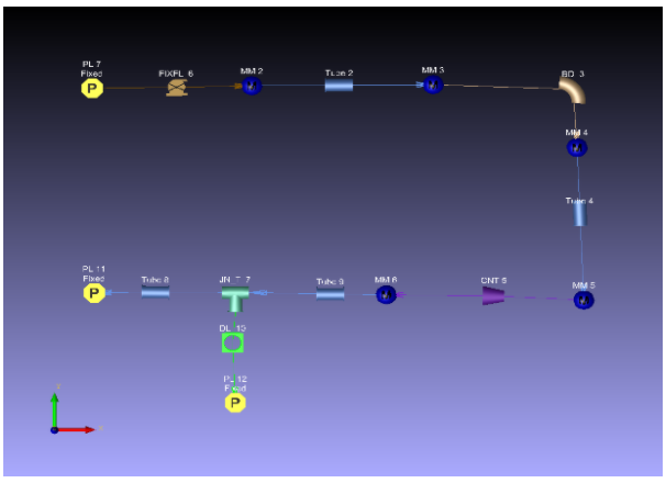
Figure: Sample Flow Network FlowSimulator model
A FlowSimulator model consists of a network of chambers and elements with defined fluid pressure, temperature, velocity, flow direction, and mixture fraction at the boundary chambers. The flow resistance characteristics of each element are defined in the model. Initial guess values for the pressures, temperatures and velocities are prescribed at the internal chambers. To complete the input, a set of general data is included, which specifies output file requirements, convergence tolerances, and solution control parameters.
In solving a model, FlowSimulator employs a relaxed Newton-Raphson solver to iteratively update internal chamber pressures and step towards the solution until flow continuity in the internal chambers is achieved within the specified tolerance. For each iteration step, flows through all elements are re-calculated based on the new set of guessed pressures. Subsequently, temperatures and velocities are re-calculated in all chambers based on the exit conditions of the elements whose flows enter each chamber. Using the difference between inflow and outflow in each internal chamber (known as chamber flow imbalance) and the characteristic resistance calculated for the elements (known as dW/dP), a new set of pressure guesses is then made and the process is repeated until the model converges or the maximum number of iterations specified is exhausted. To complete the calculation process, the flow entering or exiting each boundary chamber is calculated. When the model converges (or the run completes for other reasons, such as the user deciding not to continue running more iterations when convergence is not reached in the allotted number of iterations), the output files are written, and the run is concluded.
General Considerations
Coordinate System
FlowSimulator uses a three-dimensional coordinate system. The coordinate system is orthogonal and, in the case of inertial chambers, represents a cylindrical system about the axis of rotation. The following figure defines this coordinate system.
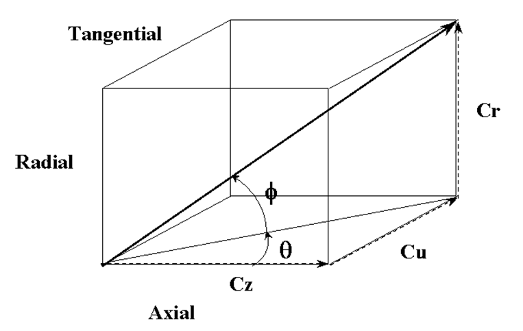
Figure:Radial coordinate system
Note: Phi is defined relative to the U-Z component vector.