Vortex Elements
Vortex General Description
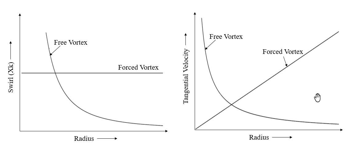
The Vortex Element in Flowsimulator typically used to model rotating flows in turbomachinery applications. It accounts for the change in radial momentum of the rotating fluid (swirl) and computes pressure rise and temperature gradients in the vortex flow. Swirl is defined as fluid tangential velocity as a fraction of the tangential velocity of the rotor. Vortex pressure ratio is defined as the ratio of the static pressure of the fluid leaving the vortex to the static pressure of the fluid entering the vortex. The vortex temperature rise is defined as the difference between the temperature of the fluid leaving the vortex and the temperature of the fluid entering the vortex. A negative temperature “rise” just signifies that the temperature leaving the vortex is lower than that entering the vortex. Unlike the vortex pressure ratio, the vortex temperature rise calculation is dependent on the type of the chamber to which vortex is attached and whether the vortex is associated with a cavity. There are 3 main categories of vortex in FlowSimulator that differ on how swirl, delta T, and pressure ratio are calculated.
- Free Vortex - the free vortex in which no torque is applied to the fluid from the vortex inlet to the vortex outlet
- Forced Vortex - forced vortex in which the fluid angular velocity about the engine centerline remains constant through the vortex.
- Cavity vortex - forced vortex which gets its pressure ratio and temperature rise from an angular momentum and energy analysis performed in the Flowsimulator cavity solver routine
Quick Guide for Vortex Creation in the GUI
Vortex elements are available under “Vortexes” section of element library in both “Compressible Gas Elements” and “Incompressible Liquid Elements”.
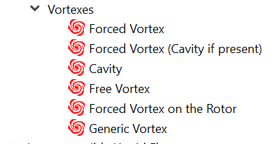
User will have to make decision on modeling a vortex as Free, Forced, or Cavity required for the model. Generic Vortex subtype has various options available (Free, Forced, Cavity, User Defined etc) to choose for calculating Pressure ratio and Delta Temperature rise. Reference Rotor, radius beginning, and end are mandatory inputs. In case you are splitting the vortex in more than one segment (segmented vortex), user can use Vortex Chamber to specify the source for Pressure and Swirl. The segmented vortex is a vortex in which the angular velocity (or the inlet angular velocity in the case of a free vortex) is defined for each of several radially defined segments from the vortex inlet to the vortex outlet.
In the Figure 1.1 Vortex Element setup, the forced vortex (No: 6) is split into three segments. The Swirl chambers are required for each segments & the radius need to be specified for each station. The Select option in vortex swirl chambers panel allows users to select chambers from the GUI. The Pick option in Radii Panel allows users to pick chambers & the corresponding chamber radius (Y Location) are updated automatically for the station radius. These options are beneficial when the model is created in association with IGES & chambers representing real locations on the geometry. This Model is available under section Exercise: Simple Cavity.
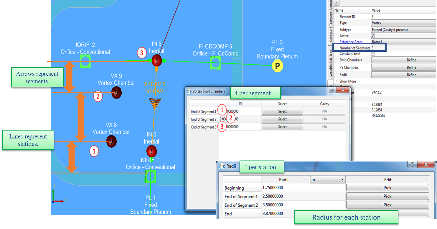
Figure 1.1: Vortex Element Setup
Vortex Inputs
Table of the inputs for the Vortex element.
| Element Specific Vortex Element Input Variables | ||
|---|---|---|
| Index | UI Name (. flo label) | Description |
| 1 | Reference Rotor (RTR_IDX) |
Reference rotor index for user-supplied swirl. Rotor 1 (database Value = 1.0): Points to general data Shaft 1 Rotor Speed (ELERPM1). Rotor 2 (database Value = 2.0): Points to general data Shaft 2 Rotor Speed (ELERPM2) Rotor 3 (database Value = 3.0): Points to general data Shaft 3 Rotor Speed (ELERPM3) |
| 2 | Number of Segments (Segments) | Number of segments for vortex element |
| 3 |
Swirl Forward. (XK_FWD) |
User-specified swirl for forward flow through the vortex. This variable is typically used for single-segment forced vortexes without swirl chambers. |
| 4 |
Swirl Reverse (XK_REV) |
User-specified swirl for reversed flow through the vortex. This variable is typically used for single-segment forced vortexes without swirl chambers. |
| 5 | Heat Input (QINV) | Heat input. QINV is heat added to (positive value) or removed from (negative value) fluid flowing through the vortex. If one or more swirl chambers are used and they are associated with a cavity, the total Q for the vortex will be the sum of the cavity Q’s and QINV. |
| 6 | Apply Chamber to Vortex Pumping (DTPMPIN) |
Flag to control pumping between the upstream chamber and the first station of the vortex. Inactive if the upstream chamber type is not inertial. This flag activates an option to calculate the temperature change due to pumping from the swirl (XK) at the upstream chamber to the specified swirl (XK) at the first station using the pumping equation. Care must be taken to be sure the inlet pumping is not double counted if this flag is set to one. 0.0: No vortex inlet temperature pumping 1.0: Calculate vortex inlet temperature pumping (Default value = 0.0) NOTE: If the swirl (XK) at the vortex inlet is the same as the swirl (XK) for station 1, there is no temperature change due to inlet pumping. |
|
7 8 |
Attenuation Fac. Z (ATTENU-Z) Attenuation Fac. R (ATTENU-R) |
Attenuation factors for the Z (axial) and R (radial) components of velocity. They specify the fraction of those velocities that will be passed from the upstream chamber through the vortex to the downstream chamber. 0.0: Full attenuation – none of the velocity is passed through 1.0: No attenuation – all the velocity is passed through. (Default value = 0.) |
| 9 | Delta T Scale Fac. (DTVSF) |
Vortex delta T scale factor. Scale factor applied when work is extracted from fluid in a vortex (temperature decreasing). Has no effect if vortex delta T is positive. (Default value = 1.0) |
| 10 | Temperature Source (FIX_T_SRC) |
Controls source temperature used for vortex pressure ratio calculations. Not used for vortexes where pressure ratio is established by a cavity. 0.0: Use static temperature based on upstream chamber based on flow direction. 1.0: Use static temperature based on user-defined upstream chamber. 2.0: Use static temperature based on user-defined downstream chamber. Some models have significantly different temperatures at the vortex inlet when flow reverses so that the vortex pressure ratio is significantly different between forward and reverse flow. For some of those models, the flow is overbalanced no matter which way the flow is chosen. In effect, there is a discontinuity and convergence are impossible. Picking a flag greater than 0 might enable convergence but users should be aware of implications on vortex pressure ratio calculations. Vortex pressure ratio discontinuities can also be caused by different XK_FWD and XK_REV. Those cases will not be helped by the above flag. (Default value = 0.0) |
| 11 |
Vortex Flow Flag (FLOW_FLG) |
Flag to control how the flow rate through the vortex element is determined. Possible values are: 0.0: Automatic approach – starts the run using the average of the net flow on upstream and downstream chambers. As the run progresses, Flow Simulator tries to determine the most stable end (upstream or downstream) of the vortex and uses the flow rate at that chamber 10.0: Always uses the average of net flow on the upstream and downstream chambers 11.0: Always uses net flow from the upstream chamber 12.0: Always uses net flow from the downstream chamber <0: A negative flow flag points to an element number from which the vortex element should get its flow rate |
| A1 | PS Chambers (PS_CHAMBERS) |
Identifies user chamber numbers for retrieving and storing intermediate vortex pressures. 0: Do not store or print intermediate pressure at this station. CHNUM: Store the pressure calculated at the intermediate station in chamber CHNUM. Vortex upstream and downstream chambers are not included, so there can be no more than (number of segments - 1) PS_CHAMBERS. PS_CHAMBERS must be vortex type chambers. |
| A2 | Swirl Chambers (SWIRL_CHAMBERS) |
Identifies user chamber numbers for retrieving and storing swirl values. 0: Use XK_FWD and XK_REV fixed swirl values. CHNUM: Use swirl stored in chamber CHNUM. For forced vortexes, there must be one swirl chamber for each segment. For free vortexes, there must be one swirl chamber for each intermediate station. The total number of swirl chambers will be (number of segments - 1). |
| A3 | Radii (RADII) |
Radial distance to each vortex station from the engine centerline. (The term station refers to the either end of a segment. Adjacent segments share a common station.) The number of stations is SEGMENTS plus one. The RADII array includes the first and last station. |
In Addition to above inputs, the generic vortex subtype requires some more additional inputs/information as explained in the table below
| Element Specific Vortex Element Input Variables | ||
|---|---|---|
| Index | UI Name (. flo label) | Description |
| 1 | Vortex Pressure Ratio Type (P_RATIO_FLG) |
Controls the choice of pressure ratio equation. 1.0: Free Vortex - Uses free vortex pressure ratio equation. 2.0: Forced (Isentropic) Vortex - Uses forced (isentropic) vortex pressure ratio equation. 3.0: Cavity (Isothermal) Vortex - Uses cavity (isothermal) vortex pressure ratio equation. 4.0: Cavity/Forced - If a cavity is present, use option 3.0; otherwise, use option 2.0. 5.0: P Ratio Equals 1 - Fixed vortex pressure ratio of 1.0 6.0: User Defined - User-specified pressure ratio |
| 2 | Vortex Delta T Type (DELTA_T_FLG) |
Controls the choice of vortex temperature change equation. 1.0: Free Vortex - Uses free vortex temperature equation. 2.0: Forced (Isentropic) Vortex - Uses isentropic forced vortex temperature equation. 3.0: Cavity (Isothermal) Vortex - Uses cavity vortex (“pumping”) temperature equation. 4.0: Cavity/Forced - If a cavity is present, use option 3.0; otherwise, use option 2.0. 5.0: Delta T = 0 - Fixed vortex temperature change of 0.0 6.0: User Defined - User-specified temperature change 7.0: Forced (On the Rotor) - Uses the forced vortex temperature equation The delta T specified in options 5 and 6 is change in absolute temperature if the upstream (as defined) chamber is inertial and change in relative temperature for other chamber types. |
| 3 | Pressure Ratio Forward Flow (PDPU_FWD) |
User-specified vortex pressure ratio for forward flow through the vortex. (Only used if P_RATIO_FLAG = 6) |
| 4 | Delta T Forward Flow (DT_FWD) |
User-specified vortex temperature rise for forward flow through the vortex. The delta T specified is change in absolute temperature if the upstream (as defined) chamber is inertial and change in relative temperature for other chamber types. (Only used if DELTA_T_FLAG = 6) |
| 5 | Pressure Ratio Reversed Flow (PDPU_REV) |
User-specified vortex pressure ratio for reversed flow through the vortex. (Only used if P_RATIO_FLAG = 6) |
| 6 | Delta T Reversed Flow (DT_REV) |
User-specified vortex temperature rise if reversed flow through the vortex. The delta T specified is change in absolute temperature if the upstream (as defined) chamber is inertial and change in relative temperature for other chamber types. (Only used if DELTA_T_FLAG = 6) |
Vortex Theory Manual
The vortex element applies physical equations that relate static pressure, total temperature, and fluid velocity at the vortex inlet with those at the vortex exit. It basically does the Pressure ratio and Temperature rise calculations based on the type of Vortex Element (Free Vortex, Forced Vortex, Forced Vortex with Cavity, Forced Vortex on Rotor, Cavity Vortex, Generic Vortex). For both the free vortex and the forced vortex, the assumption is made that the flow through the vortex is isentropic and that fluid properties are adequately represented by the specific heat ratio and the fluid gas constant as determined at the vortex inlet temperature & pressure. In the equations presented in this section, the subscript 1 denotes the vortex segment inlet, and the subscript 2 denotes the vortex segment exit. The inlet and exit of each vortex segment are referred to as “stations” in output. For a multi-segment vortex, the vortex parameters (Swirl, Pressure rise & Temperature gradients) are computed for each vortex segment and assembled for the entire segmented vortex. If there is flow reversal, then the inlet and exit radii trade places; the inlet swirl factor, pressure, and temperature are generally changed as well. However, the same vortex equations are applied.
Nomenclature:
| Vaxial: Magnitude of the axial component of the fluid velocity | Vradial: Magnitude of the radial component of the fluid velocity |
| ATZ: Attenuation Factor for Axial Velocity (Ratio of fluid axial velocity at the vortex exit to that at the vortex inlet) | ATR: Attenuation Factor for Radial Velocity (Ratio of fluid radial velocity at the vortex exit to that at the vortex inlet) |
| VTANG, ABS: Magnitude of the tangential component of the absolute fluid velocity | XK: Ratio of the fluid absolute rotational speed to the rotational reference frame (i.e. rotor) |
| R: Radius from the engine centerline | RPMF: Absolute rotational speed of the fluid (rev/min) |
| TT,ABS: Absolute total temperature of the fluid | TT,REL: Total temperature of the fluid relative to the rotational reference frame (i.e. rotor) |
| TS: Static temperature of the fluid | Ω: Rotational speed of the reference frame (i.e. rotor) for the vortex segment (rad/sec) |
| PRFWD/REV: User-specified static pressure ratio (exit / inlet) across the vortex segment | DTFWD/REV: User-specified total temperature change across the vortex segment |
| Qwin: Total Cavity windage | Cp: Specific heat of fluid |
| absolute value of mass flow rate | RHO: Density of fluid |
Subscripts:
| ABS: Absolute Frame | REL: Relative Frame |
| T: Total Quantities | S: Static Quantities |
| FWD: Forward | REV: Reverse |
| k: Index of attached non-vortex elements | n: Number of non-vortex elements attached to the downstream chamber |
| m: Number of non-vortex elements attached to the upstream chamber |
Vortex Exit Velocity Calculations
The following table provides details about how the axial, radial, and tangential components of the fluid velocity at the vortex exit are calculated. The equation(s) used to calculate tangential component of the fluid velocity at the vortex exit are determined by the type of vortex. The tangential exit velocity directly effects the vortex pressure ratio and vortex temperature rise calculations.
|
VELOCITY COMPONENT |
VORTEX TYPE (P_RATIO_FLG / DELTA_T_FLG) |
EQUATION(S) |
|---|---|---|
| Axial | ALL |  |
| Radial | ALL | 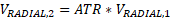 |
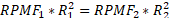
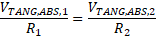
| Tangential | FREE VORTEX | 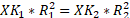
 |
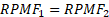
| FORCED VORTEX | 
|
|
| CAVITY VORTEX |
(See cavity section for information) |
 = velocity of air exiting
cavity
= velocity of air exiting
cavityNote: Vortex Radial and Axial Velocity Attenuation
Full Attenuation: (default): None of the axial and radial velocity passes through the vortex element to the downstream chamber. The axial and radial velocity is not driving flow through a downstream restriction.
No Attenuation: All of the axial and radial velocity passes through the vortex element to the downstream chamber. The axial and radial velocity is available to drive flow through a downstream restriction.
Vortex Pressure Ratio & Temperature Rise Calculations
Free Vortex
The Pressure ratio for Free Vortex are derived from radial equilibrium equation & the final form is given as follows
For Compressible Gas: 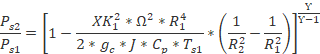
For
Incompressible Gas & Liquids: 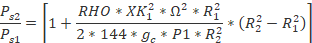
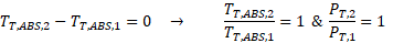
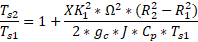
There is no change in total temperature in an isentropic free vortex. In this case, the change in static temperature is opposite and equal to the change in the dynamic temperature resulting from the change in the tangential velocity. Thus, for an isentropic free vortex we obtain
For more details about the derivations of Pressure ratio & temperature rise refer Section 2.3 of “Gas Turbines Internal Flow Systems Modeling” by Bijay Sultanian
Forced Vortex
The Pressure ratio & Temperature Rise for Forced Vortex are given as follows
For Compressible Gas: 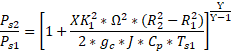
For
Incompressible Gas & Liquids: 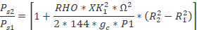
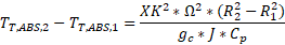
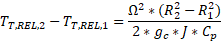
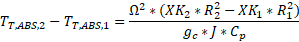
The change in total temperature in an isentropic forced vortex equals twice the change in its static temperature

For more details about the derivations of Pressure ratio & temperature rise refer Section 2.3 of “Gas Turbines Internal Flow Systems Modeling” by Bijay Sultanian
Forced Vortex on the Rotor
This vortex subtype is same as Forced vortex but differ only in calculating Temperature rise across vortex. For Forced Vortex on Rotor, change in temperature will be based on XK = 1, independent of XK specified for the vortex
.
Cavity Vortex
For the cavity vortex, the solution of fluid swirl velocity and vortex temperature rise is done in the cavity solver. Calculation of vortex pressure ratio is done in the cavity solver routine if the cavity is associated with a single vortex with all inflow at one radius and all outflow at another radius. If several different vortexes with various inflow and outflow radii are involved in a cavity, the cavity solver determines the swirl velocity of the fluid in the cavity and a single temperature rise from the mixed inlet temperature to an average fluid exit total absolute temperature. The vortex pressure ratio for each vortex is then calculated external to the cavity solver assuming an isothermal vortex at the cavity average static temperature as given below
For Compressible Gas: 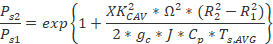
For
Incompressible Gas & Liquids:
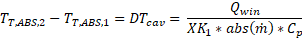
The change in total temperature in an isothermal vortex is given by
More information about cavity XK calculations & cavity windage are available in Cavity Theory Manual.
Forced Vortex (Cavity if Present)
The pressure ratio & temperature rise across vortex is calculated based on equation specified in Cavity Vortex subtype if cavity is associated with chambers else Forced vortex subtype is used
Generic Vortex
Apart from the options which are presented above (Free, Forced, Cavity), the generic vortex provides two more options for users to calculate Vortex pressure rise across any vortex segments. They are
- P ratio equals 1

- User Defined: User specified Pressure ratio for vortex segment
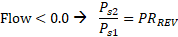
For
Forward Flow:
For Reverse Flow: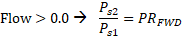
For the temperature rise calculations, in addition to Free, Forced, Cavity options, the generic vortex provides 3 more options as mentioned below
- Delta T = 0
For Inertial or Non-Rotating Frame:
 For Rotating Frame:
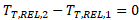
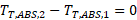
- User Defined:
For Inertial or Non-Rotating Frame:
For Forward
Flow:
For Reverse Flow:
For Rotating Frame For Forward Flow:
For Reverse Flow:

- DT_PUMPING
Note: Temperature Rise calculation Options
In Some instance, Flowsimulator automatically modifies Vortex Temperature rise calculations functions to prevent errors related to mismatch between user specified options and the swirl chamber.
For Example:
- If the user specifies Vortex Temperature rise calculations as cavity ΔT (DELTA_T_FLG = 3) and the supplied swirl chamber is not an inertial-type or vortex-type chamber or the swirl chamber does not have an associated cavity, FlowSimulator will use the DT_PUMPING for calculating temperature rise across vortex segments (DELTA_T_FLG = 8)
- If the user specifies Vortex Temperature rise calculations as cavity ΔT (DELTA_T_FLG = 3) and the supplied swirl chamber is inertial with an associated cavity, FlowSimulator will change the Temperature rise calculations to Fixed Delta T = 0 and the cavity windage is applied directly to the inertial chamber.
Temperature frame conversions
As discussed above, both the vortex inlet temperature and the vortex temperature rise depend on the Frame of reference, the chamber type to which the vortex is connected, and the rotational speed of the element with which the vortex is associated. As discussed in Chambers section, the chamber is assumed to be rotating at the speed of the element if its type is either Plenum or Momentum, while it is stationary if the chamber type is Inertial. If chambers at either end of the vortex store temperature in a different temperature frame, then temperature frame conversions are required. The following table shows the equations used when temperature frame conversions are required at the vortex inlet, exit, or both.
| CONVERSION TYPE | LOCATION | EQUATION |
|---|---|---|
| REL_TO_ABS | INLET | 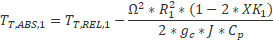 |
| EXIT | 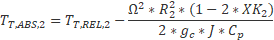 |
|
| ABS_TO_REL | INLET | 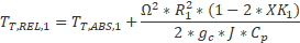 |
| EXIT | 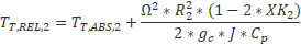 |
Vortex Flow Rate
Unlike other elements in FlowSimulator, there is no governing equation for determining Mass flow rate across Vortex. The flow rate in a vortex is determined by the flow imbalance in the chambers at each end of the vortex. The flow imbalance does not include the vortex element flow. Flow (W) entering the chamber is positive and flow exiting the chamber is negative


By Default, the Automatic Option is used to determine the flow, where solver searches for the best vortex end to use for the imbalance. There are some user controls over the method used as described below
- Automatic – (default) solver searches for the best vortex end to use for the imbalance.
- Average Up and Down – always uses both ends of vortex
- Upstream – always uses upstream chamber of the vortex
- Downstream – always uses the downstream chamber of the vortex
- Other – Uses an element (User should type in number of a more stable element number in series with the vortex element)
Vortex Outputs
The following listing provides details about vortex element output variables.
| Name | Description | Units |
|---|---|---|
| P_RATIO_FLG |
Vortex pressure ratio equation flag used based on Vortex Subtype FREE_VORTEX FORCED_VORTEX CAVITY FORCED_OR_CAVITY PRESSURE_RATIO_=_1 USER_SPECIFIED |
(flag) |
| DELTA_T_FLG |
Vortex temperature change equation flag used based on Vortex Subtype FREE_VORTEX FORCED_VORTEX CAVITY FORCED_OR_CAVITY DELTA_T_=_0 USER_SPECIFIED |
(flag) |
| Q_FLAG |
Heat input equation flag. CONSTANT |
(flag) |
| QIN |
Heat input. Positive values indicate heat added to the fluid; negative values indicate heat removed. |
BTU/s, W |
| DTVSF |
Vortex pumping scale factor. (Usually an echo of the user input unless modified inside Flow Simulator.) |
(unitless) |
| VEL_ATTEN_AX | Attenuation Factor for Axial Velocity | (unitless) |
| VEL_ATTEN_R | Attenuation Factor for Radial Velocity | (unitless) |
| VABS | Magnitude of the fluid total absolute velocity | ft/s, m/s |
| THTA_ABS | Fluid absolute tangential flow angle | rad, deg |
| VTAN_ABS | Magnitude of the fluid absolute tangential velocity | ft/s, m/s |
| VAXIAL | Magnitude of the fluid axial velocity | ft/s, m/s |
| VRAD | Magnitude of the fluid radial velocity | ft/s, m/s |
| VREL | Magnitude of the fluid total velocity relative to the element | ft/s, m/s |
| THTA_REL | Fluid tangential flow angle relative to the element | rad, deg |
| VTAN_REF | Reference frame tangential velocity | ft/s, m/s |
| VTAN_REL | Magnitude of the fluid tangential velocity relative to the element | ft/s, m/s |
| VNORM | Magnitude of the fluid total velocity relative to the element that is aligned with the element centerline | ft/s, m/s |
| STA | Vortex station number. | (index) |
| RADII | Radius to the vortex station from the engine centerline. | Inch, mm |
| PSC | Static pressure at the vortex station. | Psia, MPa |
| TTC |
Total temperature at the vortex station. Temperature reference frame specified by FRAME (below). |
deg F, deg K |
| TTC FRAME | Temperature reference frame (absolute or relative) for the vortex station. | (flag) |
| TS |
Static temperature at the vortex station. Static temperature calculation does not include axial or radial velocity terms. |
deg F, deg K |
| PS_CHMBR | Chamber identification number where static pressure for the vortex station is stored. | (flag) |
| XK |
Fluid swirl factor at the vortex station. Calculated as the ratio of the absolute tangential fluid velocity component to the rotational reference frame (REF_RPM) tangential velocity. |
(unitless) |
| XK REF_RPM | Reference frame rotational speed at the vortex station. | rev/min |
| SEG | Vortex segment number. | (index) |
| PS_RATIO | Static pressure ratio for the vortex segment. | (unitless) |
| DELTA_TT | Total temperature change across the vortex segment. | deg F, deg K |
| XK_CHMBR | Chamber identification number where XK (swirl) for the vortex station is stored. | (flag) |
| DELTA_T_FRAME |
Temperature reference frames of the vortex segment inlet and exit. ABS_TO_ABS ABS_TO_REL REL_TO_ABS REL_TO_REL |
(flag) |
| DTT_CAV | Total temperature change across the vortex segment due to cavity windage. | deg F, deg K |
| DTT_CV_PMP | Total temperature change across the vortex segment to cavity pumping. This is displayed only for multiple outflow cavities. | deg F, deg K |
| DTT_VTX | Total temperature change across the vortex segment to free or forced vortex pumping. | deg F, deg K |
| DTT_CHQ | Total temperature change across the vortex segment to chamber heat input (QIN). | deg F, deg K |
| DTT_QNV | Total temperature change across the vortex segment due to vortex heat input (QINV). | deg F, deg K |
| DTT_FIX | Total temperature change across the vortex segment due to user-specified temperature change. | deg F, deg K |
References
- von Karman, T., On Laminar and Turbulent Friction, 1921 (NACA TM 1092, 1945)
- Da Soghe, R., Facchini, B., Innocenti L. and Micio, M., Analysis of Gas Turbine Rotating Cavities by a One-Dimensional Model: Definition of New Disk Friction Coefficient Correlations Set, ASME Journal of Turbomachinery, Vol 133, 2011.
- Da Soghe, R., Innocenti L., Andreini A., and Poncet, S., Numerical benchmark of turbulence modeling in gas turbine rotor-stator system, ASME Turbo Expo 2010, GT2010-22627, 2010.
- Da Soghe, R., Facchini, B., Innocenti L. and Micio, M., Some Improvements in a Gas Turbine Stator-Rotor Systems Core-Swirl Ratio Correlation, International Journal of Rotating Machinery, Volume 2012, Article ID 853767, 2012.
- Owen, J.M. and Pincombe, J.R., Velocity measurements inside a rotating cylindrical cavity with a radial outflow of fluid, Journal of Fluid Mechanics, Vol. 99(1), pages 111 – 127, 1980.
- Owen, J.M., Pincombe, J.R. and Rogers R. H., Source-sink flow inside a rotating cylindrical cavity, Journal of Fluid Mechanics, Vol. 155(1), pages 233 – 265, 1985.
- Bijay Sultanians “Gas Turbines Internal Flow Systems Modeling” Section 2.3.1