Spline Seal Element
Spline Seal Element General Description & Quick Guide
Spline Seal element routine calculates the Leakage Flowrate across the seal based on the Effective gap.
![]()
There are various subtypes/configuration of Spline Seal element available in FlowSimulator. They are
- Constant Effective Gap
- Chute and Segment Gaps
- Const. Eff., Chute & Segment Gaps
The Seal elements are available only in Compressible Gas Elements section. The method for calculation of effective area varies based on the subtype of spline seal element chosen.
Spline Seal Element Inputs
Table of the inputs for the Spline Seal Element.
| Element Specific Spline Seal Element Input Variables | ||
|---|---|---|
| Index | UI Name (. flo label) | Description |
| 1 | Subtype (SUB_TYPE) |
The element subtype controls the spline seal type. 7.0: Constant Effective Gap 8.0: Chute and Segment Gaps 9.0: Const. Eff., Chute & Segment Gaps |
| 4 | Length (LENGTH) |
Length of the spline seal or seal segment Used for subtypes 7 & 9 Must be > 0 |
| 6 | Element Inlet Orientation: Tangential Angle (THETA) |
Angle between the element centerline at the entrance of the element and the reference direction. If the element is rotating or directly connected to one or more rotating elements, the reference direction is defined as parallel to the engine centerline and the angle is the projected angle in the tangential direction. Otherwise, the reference direction is arbitrary but assumed to be the same as the reference direction for all other elements attached to the upstream chamber.
THETA for an element downstream of a plenum chamber has no impact on the solution except to set the default value of THETA_EX. (See also THETA_EX) |
| 7 | Element Inlet Orientation: Radial Angle (PHI) |
Angle between the element centerline at the entrance of the element and the THETA direction. (spherical coordinate system)
PHI for an element downstream of a plenum chamber has no impact on the solution except to set the default value of PHI_EX. (See also PHI_EX) |
|
8 9 10 |
Exit K Loss: Axial (K_EXIT_Z) Tangential (K_EXIT_U) Radial (K_EXIT_R) |
Head loss factors in the Z, U, and R directions based on the spherical coordinate system of theta and phi. (Default value provides no loss).
Refer General solver theory sections for more details about this input |
| 11 | Portion of Ustrm Chamb. Dyn. Head Lost (DQ_IN) | Inlet dynamic head loss. Refer General solver theory sections for more details about this input |
| 12 | Heat Input (QIN) |
Heat input. QIN is heat added to (positive values) or removed from (negative) the fluid flowing through the orifice. In cases where multiple flow streams are modelled by a single element (i.e. NED and NLU not equal to 1), the value of QIN should be set to model the heat flow from only one of the restrictions. |
| 13 | Effective Gap (EFF_GAP) |
Effective Gap of the spline seal Used for subtypes 7 & 9 Must be >= 0 |
| 16 | Segment Gap (SEG_GAP) |
Segment Gap of the spline seal Used for subtypes 8-9 Must be >= 0 |
| 17 | Unprotected Length (UNP_LENGTH) |
Unprotected Length of the spline seal Used for subtypes 8-9 Must be >= 0 |
| 18 | Groove Depth (GRV_DEPTH) |
Groove Depth of the spline seal Used for subtypes 8-9 Must be >= 0 |
| 19 | Groove Width (GRV_WDTH) |
Groove Width of the spline seal Used for subtypes 8-9 Must be >= 0 |
| 20 | Spline Thickness (SPL_WDTH) |
Spline Width of the spline seal Used for subtypes 8-9 Must be >= 0 |
| 21 | Spline Thickness (SPL_THK) |
Spline Thickness of the spline seal Used for subtypes 8-9 Must be >= 0 |
| 22 | Chute Area Multiplier (CHUTE_M) |
Chute Area Multiplier of the spline seal Used for subtypes 8-9 Must be >= 0 |
| 23 | Discharge Coefficient (CD_G_AND_C) |
Discharge coefficient of Chute Area Used for subtypes 8-9 Must be >= 0 |
Spline Seal Element Theory Manual
| Nomenclature: | |
| W: Mass flow rate | Specific heat Ratio |
| A: Effective area | R: Gas Constant |
| Tt: Total Temperature | gc: Gravitational Constant |
| Pt: Total pressure | |
| Ps: Static pressure | |
| MN: Vena Contracta Mach Number | |
| Subscripts: | |
| up: Upstream station | dn: Downstream station |
Calculation of Seal Flow Rate
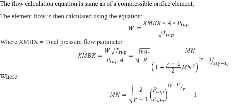
Calculation of EFFECTIVE AREA (SUBTYPES 7-9)
Constant Effective Gap
![]()
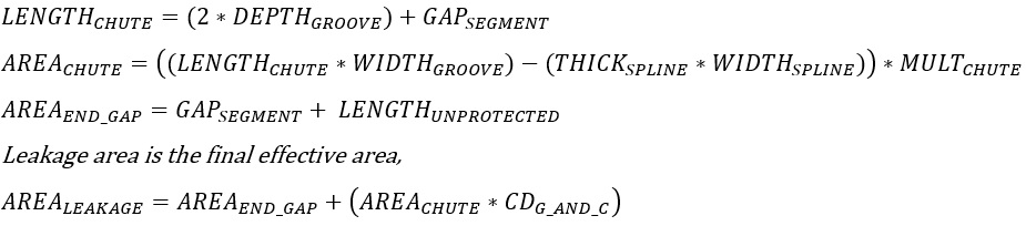
Chutes and Segment Gaps
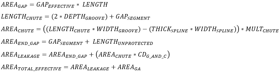
Constant Effective Gap & Chutes and Segment Gaps
Additional Momentum Loss
For Additional Momentum loss, Portion of Upstream Dynamic Head loss, Exit K Loss refer Solver General theory section.
Spline Seal Element Outputs
The following listing provides details about Spline Seal element output variables.
This table provides details about the output variables specific to the following spline seal subtypes (7-9):
| Name | Description | Units |
|---|---|---|
| CHUTE_A |
Chute Area of the spline seal Spline Seal Types:
CHUTE_A = ((CHUTE_LENGTH * GROOVE_WIDTH) – (SPLINE_THICK * SPLINE_WIDTH)) * CHUTE_MULT Where: CHUTE_LENGTH = (2 * GROOVE_DEPTH) + SEGMENT_GAP |
inch2, m2 |
| END_GAP_A |
End Gap Area of the spline seal Spline Seal Types:
END_GAP_A = SEGMENT_GAP * UNP_LENGTH |
inch2, m2 |
| CD_G_AND_C |
Discharge coefficient of Chute Area Spline Seal Types:
(An echo of the user input) |
(fraction) |
| LEAKAGE_A |
Leakage Area of the spline seal Spline Seal Types:
LEAKAGE_A = END_GAP_A + (CHUTE_A * CD_G_AND_C) |
inch2, m2 |
| GAP_EFF |
Effective Gap of the spline seal Spline Seal Types:
(An echo of the user input EFF_GAP) |
inch, mm |
| LENGTH |
Length of the spline seal Spline Seal Types:
(An echo of the user input) |
inch, mm |
| GAP_AREA |
Gap Area of the spline seal Spline Seal Types:
GAP_AREA = GAP_EFF * LENGTH |
inch2, m2 |
| EFFECTIVE_AREA or TOTAL_EFF_AREA |
Total effective area of the spline seal. (Definition varies based on spline seal type chosen) Spline Seal Types:
|
inch2, m2 |
This table provides details about the output variables common to all spline seal types:
| Name | Description | Units |
|---|---|---|
| PTS | Driving pressure relative to the rotational reference frame (i.e. rotor) at the restriction inlet. | psi, mPa |
| PTEX | Total pressure relative to the rotational reference frame (i.e. rotor) at the restriction exit including supersonic effects. | psi, mPa |
| PSEX |
Static pressure relative to the rotational reference frame (i.e. rotor) at the restriction exit. Limited by critical pressure ratio for supersonic flows. |
psi, mPa |
| PSEB | Effective sink (static) pressure downstream of the restriction. | psi, mPa |
| TTS | Total temperature of fluid relative to the rotational reference frame (i.e. rotor) at the restriction inlet. | deg F, K |
| VCMN | Fluid Mach number relative to the rotational reference frame (i.e. rotor) at the vena contracta. | (unitless) |
| VXA | Fluid velocity relative to the rotational reference frame (i.e. rotor) at the restriction exit before heat input (QIN) effects. | ft/s, m/s |
| EXMN | Fluid Mach number relative to the rotational reference frame (i.e. rotor) at the restriction exit before heat input (QIN) effects. | (unitless) |
| QIN |
Heat input. Positive values indicate heat added to the fluid; negative values indicate heat removed. |
BTU/s, W |
| DT | Change in total temperature relative to the rotational reference frame (i.e. rotor) due to heat input (QIN). | deg F, K |
| TEX | Total temperature relative to the rotational reference frame (i.e. rotor) at the restriction exit. | deg F, K |
| VEX | Fluid velocity relative to the rotational reference frame (i.e. rotor) at the restriction exit including heat input (QIN) effects. | ft/s, m/s |