Element Momentum Loss: Upstream Chamber Dynamic Head Loss
General Description
Most Flow Simulator elements are “restrictive” type elements that calculate a flowrate based on a pressure upstream of the element, the pressure downstream of the element, and a flow resistance. This document describes how the user can make adjustments to the pressure upstream of the element. The pressure upstream of the element is also called the source pressure or driving pressure for the element.
Most elements will not need an adjustment to the upstream pressure using the inputs described here. It is better to rely on proper element orientation inputs and proper flow resistance inputs (Cd, Inlet K etc..).
Upstream Chamber Dynamic Head Loss in the GUI
The user input for the upstream chamber dynamic head loss can be found in the advanced options section of restrictive type elements.
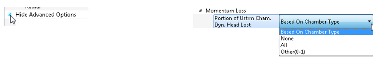
Based on Chamber Type = Inertial chamber behaves like All as described below. All other chambers use None as described below. Not all elements have the Based-on Chamber Type option.
None = Do not reduce upstream chamber dynamic head.
All = Remove all the upstream chamber dynamic head. In other words, use the static pressure.
Other (0-1) = Input a number between 0 (behaves like None) and 1 (behaves like All).
Upstream Chamber Dynamic Head Loss Theory
Flow Rate Calculation
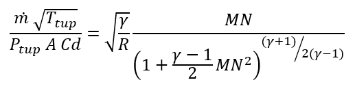
A typical compressible flowrate is calculated using the following “flow function” equation:
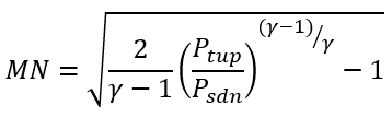
The Mach number (MN) is related to the pressure ratio using
A typical incompressible flowrate is calculated using the following:
![]()
Dynamic Head Adjustment
Ptup is the element source pressure. Ptup is modified using the following equation
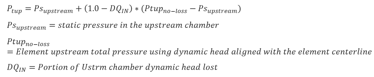
Note that the element upstream total pressure is first adjusted based on the element orientation. The dynamic head only uses the velocity that is aligned with the element centerline. The DQin adjustment is only applied after the orientation is taken into account.
Related Element Inputs for upstreamchamber dynamic head loss
The user entry is labeled DQ_IN in the database (.flo) file.
| Element Input Variables | ||
| Index | UI Name (.flo label) | Description |
| Varies with Element | Portion of UStrm Cham. Dyn. Head Lost (DQ_IN) |
Inlet dynamic head loss. Valid range is 0.0 to 1.0 inclusive. An entry outside this range will cause a warning message and the value used will be 0 or 1 (whichever value is closest to the entry). If DQ_IN > 0 and the upstream chamber has a positive component of relative velocity aligned with the centerline of the orifice, the driving pressure will be reduced by the equation:
(Default value = 0 Or None) |
Related Element Outputs for upstreamchamber dynamic head loss
Outputs in file with “res” extension. Output units controlled by user setting in “Output Control” panel.
| Name | Description | Units ENG, SI |
|---|---|---|
| PTS | Driving pressure relative to the rotational reference frame (i.e. rotor) at the restriction inlet. | Psia, MPa |
| DQIN | Portion of UStrm Cham. Dyn. Head Lost | none |